A multi-stage series displacement heat exchange system

A technology of heat exchange system and heat exchange plate, which is applied in the field of heat exchange, can solve the problem that the evaporator cannot start working, etc., and achieve the effect of increasing temperature difference, reducing pressure difference, and improving efficiency

Active Publication Date: 2018-10-09
浙江柿子新能源科技有限公司
View PDF8 Cites 0 Cited by
  • Summary
  • Abstract
  • Description
  • Claims
  • Application Information

AI Technical Summary

Problems solved by technology

The premise for the evaporator to work is that the temperature difference between the internal working fluid and the external environment is greater than 8 degrees, and the evaporator cannot start working at all.

Method used


Image

  • A multi-stage series displacement heat exchange system
  • A multi-stage series displacement heat exchange system
  • A multi-stage series displacement heat exchange system

Examples


Embodiment 1

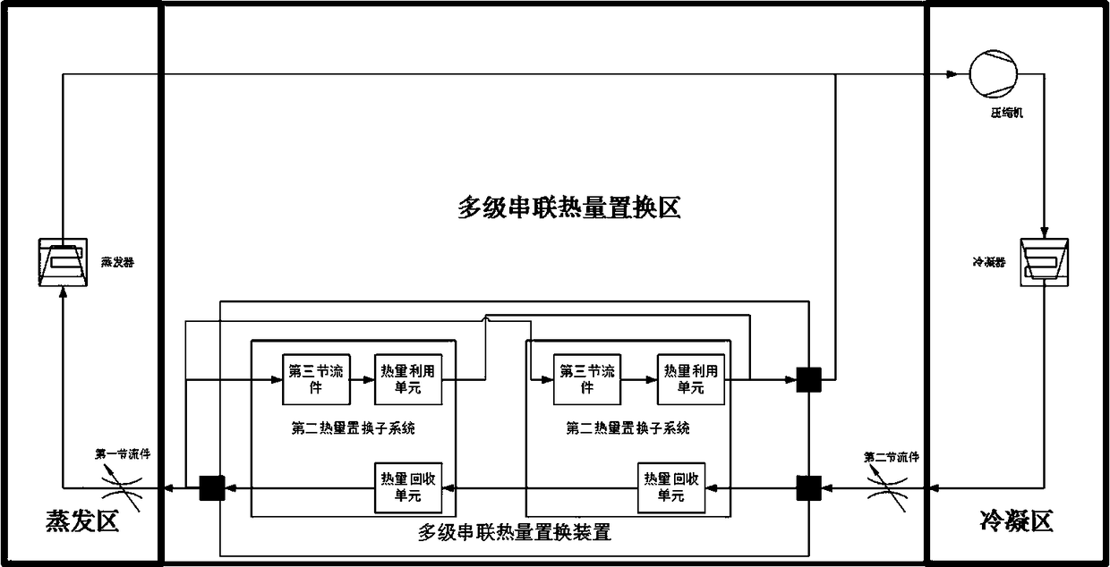
[0040] Such as Figure 4 It is a multi-stage series displacement heat exchange system, which includes a compressor, a condenser, an evaporator, a first throttling piece, a second throttling piece, and a multistage series heat displacement device connected through a working medium flow channel. The outlet of the compressor is connected to the inlet of the condenser, the outlet of the condenser is connected to the inlet of the second throttling member, the outlet of the second throttling member is connected to the inlet of the multi-stage series heat replacement device, and the first outlet of the multi-stage series heat replacement device The inlet of the first throttle is connected, the outlet of the first throttle is connected with the inlet of the evaporator, and the outlet of the evaporator is connected with the inlet of the compressor. Place the condenser in a closed environment such as a room that needs to be heated, and place the evaporator outside the closed environment...

Embodiment 2

[0049] Such as Figure 5 It is a multi-stage series displacement heat exchange system, which includes a compressor, a condenser, an evaporator, a first throttling piece, a second throttling piece, and a multistage series heat displacement device connected through a working medium flow channel. Among them, the evaporator includes an ordinary evaporator and a heat collecting plate (a heteropolymer heat absorbing plate that absorbs heat passively). The outlet of the compressor is connected to the inlet of the condenser, the outlet of the condenser is connected to the inlet of the second throttling member, the outlet of the second throttling member is connected to the inlet of the multi-stage series heat replacement device, and the first outlet of the multi-stage series heat replacement device The inlet of the first throttle is connected, the outlet of the first throttle is connected with the inlet of the evaporator, and the outlet of the evaporator is connected with the inlet of ...

Embodiment 3

[0053] Such as Figure 6 It is a multi-stage series displacement heat exchange system, which includes a compressor, a condenser, an evaporator, a first throttling piece, a second throttling piece, and a multistage series heat displacement device connected through a working medium flow channel. Among them, the evaporator includes an ordinary evaporator and a heat collecting plate (a heteropolymer heat absorbing plate that absorbs heat passively). The outlet of the compressor is connected to the inlet of the condenser, the outlet of the condenser is connected to the inlet of the second throttling member, the outlet of the second throttling member is connected to the inlet of the multi-stage series heat replacement device, and the first outlet of the multi-stage series heat replacement device The inlet of the first throttle is connected, the outlet of the first throttle is connected with the inlet of the evaporator, and the outlet of the evaporator is connected with the inlet of ...


PUM


Abstract

The invention relates to the technical field of heat exchange, in particular to a multi-stage series displacement heat exchange system. It includes an evaporator, a compressor, a condenser, and a first throttling member connected through a working fluid channel; the outlet of the evaporator is connected to the inlet of the compressor, and the outlet of the compressor is connected to the condenser Inlet, the outlet of the condenser is connected to the inlet of the first throttle, and the outlet of the first throttle is connected to the inlet of the evaporator; it is characterized in that: the outlet of the condenser and the first A multi-stage series heat exchange area is arranged between the inlets of the throttling element. The multi-stage series heat replacement area established between the condenser and the first throttling member isolates the condensation area and the evaporation area of ​​the system, and at the same time enhances condensation, isolates the influence of condensation waste heat on the evaporation area, making the system Energy efficiency is greatly improved.

Description

technical field [0001] The invention relates to the technical field of heat exchange, in particular to a multi-stage series displacement heat exchange system. Background technique [0002] Such as figure 1 , traditional air conditioning and heat pump heating / refrigeration systems include compressors, condensers, throttling parts, and evaporators. Compressed gas with high temperature and high pressure flows through the condenser to release heat, and finally enters the evaporator after being depressurized by the throttle. The working medium continuously absorbs and releases heat during the circulation process in the system to realize system heating / cooling. [0003] When the heating / refrigerating system is used for heating, the condenser is installed in the environment that needs to be heated, and the working fluid absorbs the heat in the environment where the evaporator is located in the evaporator, and is transported to the condenser through the working medium flow channel...

Claims


Application Information

Patent Timeline
Patent Type & Authority Patents(China)
IPC IPC(8): F25B1/00F25B41/06F25B41/39
CPCF25B1/00F25B2400/05F25B41/30
Inventor 唐玉敏虞红伟
Owner 浙江柿子新能源科技有限公司
Why Eureka
Try Eureka