Support for rectifying wheel rims

A wheel rim and underframe technology, which is applied in the direction of wheels, wheel assembly equipment, vehicle parts, etc., can solve the problems of low efficiency, slow correction speed, deformation of the wheel rim, etc., and achieve high efficiency, high correction accuracy, and easy operation simple effect

CN105946455AInactive Publication Date: 2016-09-21颜秋羊
5 Cites 0 Cited by

Patent Information

Authority / Receiving Office
CN · China
Patent Type
Applications(China)
Current Assignee / Owner
Publication Date
2016-09-21
Estimated Expiration
Not applicable · inactive patent

Smart Images

  • Figure 1
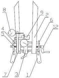
    Figure 1
  • Figure 2
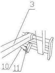
    Figure 2
  • Figure 3
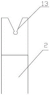
    Figure 3
Patent Text Reader

Abstract

The invention discloses a support for rectifying wheel rims, and relates to wheel rectifying devices. The support comprises a base frame, an upright rod and an adjusting frame. Two slide rails and a left-and-right threaded lead screw are arranged on the base frame and are parallelly arranged, and two ends of each slide rail and two ends of the left-and-right threaded lead screw sequentially penetrate connecting plates perpendicular to the base frame; one end of the adjusting frame is connected with the corresponding slide rail, and the other end of the adjusting frame is connected with a dial gauge stand; a deviation adjusting gauge and a V-shaped block are arranged on the dial gauge stand; an adjusting rod is arranged at the lower end of the adjusting frame; an adjusting nut is arranged on the adjusting rod; a crank handle is connected with the left-and-right threaded lead screw by the connecting plate on a side of the base frame; a fixing groove which is formed by means of cutting is formed in the upper end of the upright rod; the upright rod is a 304 stainless steel upright rod; the support is an aluminum alloy support. The support has the advantages that the wheel rims can be quickly rectified by the aid of the support, and the support is high in efficiency and rectifying accuracy and easy to operate.
Need to check novelty before this filing date? Find Prior Art

Description

technical field

[0001] The invention relates to the field of wheel straightening devices, in particular to a bracket used for wheel rim straightening. Background technique

[0002] The wheel rim is deformed due to insufficient tire pressure or accidental impact. At the same time, there are many types of wheel rims. After the spokes are placed between the rim and the hub, it is necessary to adjust the tightness of the spokes to correct the wheel. At present, the roundness of the rim is usually corrected by visual inspection. This method is slow and inefficient, and the correction accuracy is largely dependent on the level of technicians, and the correction accuracy cannot be guaranteed. SUMMARY OF THE INVENTION

[0003] The purpose of the present invention is to aim at the defects and deficiencies of the prior art, to provide a bracket for wheel rim correction, which has the advantages of quick correction of the wheel rim, high efficiency, simple operation and high correcti...

Examples

Embodiment Construction

[0015] The present invention will be described in detail below with reference to the accompanying drawings and specific embodiments, wherein the exemplary embodiments and descriptions are only used to explain the present invention, but are not intended to limit the present invention.

[0016] like figure 1 , figure 2 , image 3 As shown, this specific embodiment adopts the following technical solutions: a bracket for wheel rim correction, which includes a base frame 1, a vertical rod 2 and an adjustment frame 3, and the base frame 1 is provided with two slide rails 4 And the positive and negative threaded screw 5, which are placed in parallel, and the two ends are successively penetrated into the connecting plate 6 perpendicular to the chassis, the positive and negative threaded screw 5 is arranged between the two slide rails 4, the described One end of the adjustment frame 3 is connected with the slide rail 4, and the other end is connected with the watch frame 7. The watc...