Check patentability & draft patents in minutes with Patsnap Eureka AI!

Switch module and wall switch

A switch module and button technology, which is applied in the field of switch modules, can solve the problems of insufficient operability of button handles and reduced operability of button handles, etc.

Active Publication Date: 2016-09-28
PANASONIC INTELLECTUAL PROPERTY MANAGEMENT CO LTD
View PDF7 Cites 0 Cited by
  • Summary
  • Abstract
  • Description
  • Claims
  • Application Information

AI Technical Summary

Problems solved by technology

[0004] However, the above-mentioned piano handle switch has a problem that the operability of the button handle is insufficient
Specifically, each time the button handle is pressed, the relative position (distance) between the linear protrusion formed on the front surface of the button handle and the sliding cam is different, which results in the operability of the button handle reduce

Method used


Image

  • Switch module and wall switch
  • Switch module and wall switch
  • Switch module and wall switch

Examples


Embodiment Construction

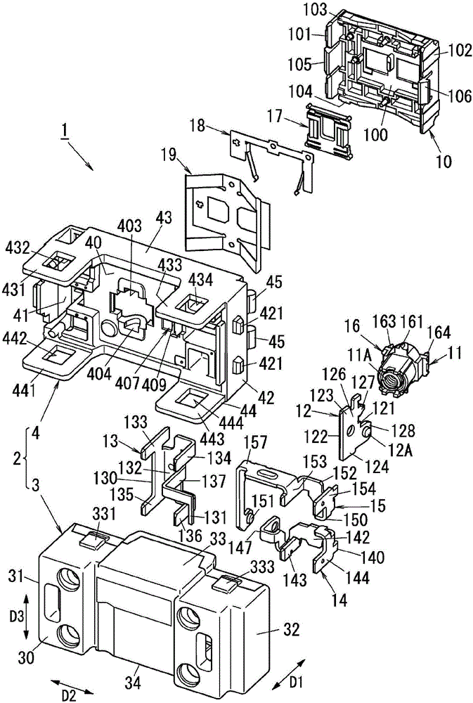
[0022] figure 1 A switch module in an embodiment of the invention is shown. First, the main components of the embodiment will be described.

[0023] Such as figure 1 As shown, the switch module 1 in the embodiment includes a button 10 , a reversing mechanism 11 , a movable terminal board 12 and a return spring 19 . The button 10 is arranged on a first side in the first direction D1, while the return spring 19 is arranged on a second side in the first direction D1.

[0024] exist figure 1 In the example of , the upper right side and the lower left side correspond to the first side and the second side of the first direction D1 respectively. The first direction D1 corresponds to the depth direction of the switch module 1 . The "front" of the switch module 1 is defined by the first side of the first direction D1 on which the button 10 is arranged. In short, in the embodiment, the first side and the second side of the first direction D1 correspond to "front side" and "rear si...


PUM


Abstract

A switch module (1) includes a push-button (10), a returning spring (19), a movable terminal plate (12) and a reversing mechanism (11). The movable terminal plate (12) is disposed on an opposite side of the returning spring (19) from the push-button (10) in the first direction (D1). The movable terminal plate (12) has a first and second ends (121 and 122) on first and second sides of the first direction (D1). The returning spring (19) is disposed to, whenever the push-button (10) is pressed and then released, return the push-button (10) to a position before the push-button (10) is pressed. The second end (122) of the movable terminal plate (12) and a center of the returning spring (19) are placed at positions corresponding to a position of a projection (107) of the push-button (10) in the first direction (D1).

Description

technical field [0001] The present invention relates generally to switch modules and wall switches, and more particularly to a switch module and a wall switch comprising the same, the switch module being configured such that whenever a button of the switch module is pressed, the The button returns to the position it was in before it was pressed. Background technique [0002] For example, JP2004-296231A discloses a piano handle (type) switch. The piano grip switch includes a switch main body and a piano grip (operating blade). The switch main body includes a housing and a switching mechanism accommodated in the housing. The switching mechanism includes a button handle (button) arranged on a front surface of the housing and configured to be pressed. The switching mechanism is configured such that whenever the button handle is pressed, the contacts of the switching mechanism open and close. [0003] The switch mechanism includes contacts (movable contacts and fixed contacts...

Claims


Application Information

Patent Timeline
Patent Type & Authority Applications(China)
IPC IPC(8): H01H21/24
CPCH01H21/245H01H13/60H01H21/42H01H23/205
Inventor 奥野裕寿马场一哉多田英人草川隆司今井克哉
Owner PANASONIC INTELLECTUAL PROPERTY MANAGEMENT CO LTD
Features
  • R&D
  • Intellectual Property
  • Life Sciences
  • Materials
  • Tech Scout
  • Unparalleled Data Quality
  • Higher Quality Content
  • 60% Fewer Hallucinations
Learn More