Check patentability & draft patents in minutes with Patsnap Eureka AI!

Dynamic seal for fuel injector needle check

A fuel injector and check valve technology, which is applied to fuel injection devices, special fuel injection devices, engine components, etc., can solve problems such as understanding or solving

Active Publication Date: 2016-10-26
CATERPILLAR INC
View PDF7 Cites 2 Cited by
  • Summary
  • Abstract
  • Description
  • Claims
  • Application Information

AI Technical Summary

Problems solved by technology

However, none of the problems and challenges associated with different liquid and gaseous fuel pressures, such as leakag

Method used


Image

  • Dynamic seal for fuel injector needle check
  • Dynamic seal for fuel injector needle check
  • Dynamic seal for fuel injector needle check

Examples


Embodiment Construction

[0021] Aspects of the invention will now be described with reference to the drawings, wherein like reference numerals refer to like elements throughout, unless otherwise indicated.

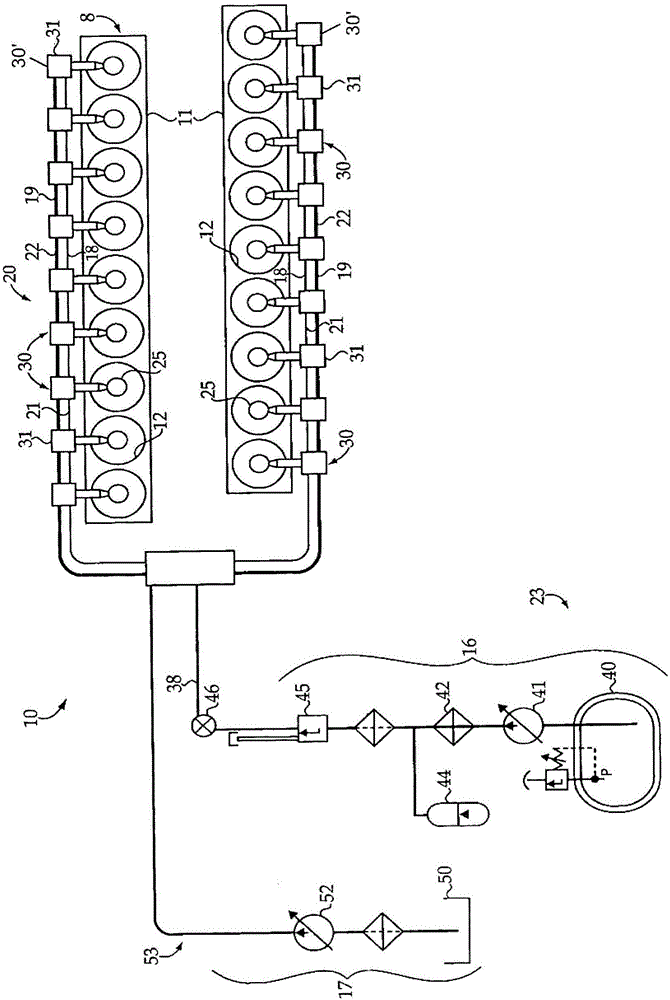
[0022] Figure 1-3 Engine 8 and dual fuel engine system 10 are shown. Engine 8 may include an engine housing 11 which may define a plurality of engine cylinders 12 . Dual fuel engine system 10 may include dual fuel system 20 mounted to engine housing 11 of engine 8 . Dual fuel system 20 may include at least one fuel injector 25 positioned to inject directly into at least one cylinder of plurality of engine cylinders 12 . Gaseous fuel common rail 21 and liquid fuel common rail 22 may be fluidly connected to each of at least one fuel injector 25 and are part of gaseous fuel subsystem 23 and liquid fuel subsystem 53 , respectively, of dual fuel system 20 . Liquid fuels may include distillate diesel fuel, biodiesel, dimethyl ether, gasoline, ethanol, liquefied natural gas, liquefied propane, combin...


PUM

PropertyMeasurementUnit
Radial depthaaaaaaaaaa

Abstract

The invention relates to a dynamic seal for a fuel injector needle check. A fuel injector includes an injector body defining a liquid fuel passage, a gaseous fuel passage, and a first guide bore; a gaseous fuel check guided within the first guide bore between a retracted position and an advanced position to selectively open and block, respectively, fluid communication between the gaseous fuel passage and a gaseous fuel nozzle outlet; and a sleeve seal seated within the first guide bore, the sleeve seal having an inner surface defining a sleeve seal bore therethrough, and at least a portion of the gaseous fuel check is disposed within the sleeve seal bore; an outer surface of the sleeve seal including a first portion and a second portion, the first portion being disposed closer to a longitudinal axis of the sleeve seal bore along a radial direction than the second portion.

Description

technical field [0001] The present invention relates generally to a fluid injector, and more particularly to a sleeve seal for a fuel injector. Background technique [0002] Reciprocating internal combustion (IC) engines are known for converting chemical energy stored within a fuel supply into mechanical shaft power. A fuel-oxidizer mixture is received within a variable volume of an IC engine defined by a piston translating within a cylinder bore. The fuel-oxidizer mixture is combusted in a variable volume to convert chemical energy from the mixture into heat. In turn, the expansion of the products of combustion within the variable volume performs work on the piston which can be transferred to the output shaft of the IC engine. [0003] In a conventional direct injection compression ignition engine, most, if not all, of the fuel is injected into the variable volume with a short ignition delay time before the desired ignition timing. In other compression ignition engines, ...

Claims


Application Information

Patent Timeline
IPC IPC(8): F02M43/04F02M21/02F02M61/10F02M47/02F02M43/00
CPCF02M21/0248F02M21/0251F02M21/0263F02M43/00F02M43/04F02M47/027F02M61/10F02D19/0694F02D19/10F02M61/12F02M2200/16F02M2200/44Y02T10/30
Inventor 金会山
Owner CATERPILLAR INC
Features
  • R&D
  • Intellectual Property
  • Life Sciences
  • Materials
  • Tech Scout
  • Unparalleled Data Quality
  • Higher Quality Content
  • 60% Fewer Hallucinations
Learn More