Miniaturized and tunable broadband phase-stable fiber delay line

A fiber optic delay line and broadband technology, applied in the field of broadband phase-stable fiber delay lines, can solve problems such as complex structure, poor repeatability, and sensitivity to temperature changes, and achieve short-term application effects

Active Publication Date: 2019-02-15
INST OF SEMICONDUCTORS - CHINESE ACAD OF SCI
View PDF4 Cites 0 Cited by
  • Summary
  • Abstract
  • Description
  • Claims
  • Application Information

AI Technical Summary

Problems solved by technology

[0005] The purpose of the present invention is to provide a miniaturized and tunable broadband phase-stable optical fiber delay line, which is mainly aimed at solving the problem that the traditional optical fiber delay line is sensitive to temperature changes and the phase drift of the broadband microwave signal is serious; at the same time, it is also necessary to solve the problem of active temperature The control or feedback compensation optical fiber phase-stable delay line is bulky, complex in structure, and poor in repeatability

Method used


Image

  • Miniaturized and tunable broadband phase-stable fiber delay line
  • Miniaturized and tunable broadband phase-stable fiber delay line

Examples


Embodiment Construction

[0020] specific implementation plan

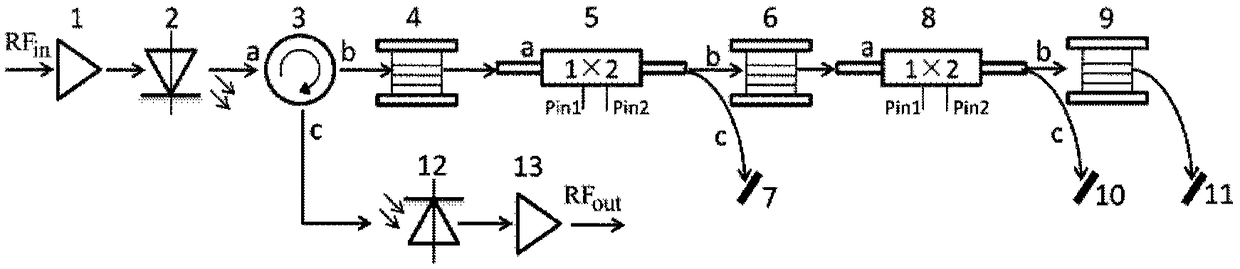
[0021] see figure 1 As shown, the present invention provides a miniaturized and tunable broadband phase-stable fiber delay line, comprising: a first low-noise microwave amplifier 1, a broadband directly modulated laser 2, an optical circulator 3, a first single-mode fiber 4, a first Magneto-optical switch 5, second single-mode optical fiber 6, first optical fiber reflector 7, second magneto-optical switch 8, third single-mode optical fiber 9, second optical fiber reflector 10, third optical fiber reflector 11, broadband photoelectric detection Device 12 and the second low noise microwave amplifier 13; Wherein:

[0022] The output port of the first low-noise microwave amplifier 1 is connected to the electrical input port of the broadband direct modulation laser 2, and the first low-noise microwave amplifier 1 is used to amplify the microwave signal power, compensate system attenuation, and reduce the noise figure of the link ;

[0023] T...


PUM

PropertyMeasurementUnit
electrical bandwidthaaaaaaaaaa

Abstract

The invention provides a miniaturized tunablebroadband stable-phase optical fiberdelay line. The miniaturized tunablebroadband stable-phase optical fiberdelay line comprises a first low-noise microwaveamplifier, a broadbanddirectly modulated laser, an optical circulator, a first single mode fiber, a first magneto-optical switch, a second single mode fiber, a first fiber reflecting mirror, a second magneto-optical switch, a third single mode fiber, a second fiber reflecting mirror, a third fiber reflecting mirror, a broadbandphotoelectric detector and a second low-noise microwaveamplifier. The problem that a traditional optical fiberdelay line is sensitive to temperature change and transmissionbroadbandmicrowave signalphase drift is severe is mainly solved. In addition, the problem that an active temperature control or feedback compensation type optical fiber stable-phasedelay line is cumbersome, complicated in structure and poor in repeatability is also solved.

Description

technical field [0001] The invention relates to the field of microwave photonic links and microwave photonic signal processing, in particular to a miniaturized and tunable broadband phase-stable fiber delay line. Background technique [0002] The delay line is the basic unit to realize the true time delay of broadband microwave signal. Compared with the traditional microwave electrical delay line, the optical fiber delay line has excellent performances such as large time-bandwidth product, low loss, small size, light weight and anti-electromagnetic interference. It has caused extensive research and application in the fields of radar signal processing and electronic countermeasure system. . However, the basic unit single-mode fiber in the optical delay line system is very sensitive to temperature changes, and its delay drift is about 35ps / km°C, which is equivalent to a phase drift of 121° / km / °C for a microwave carrier frequency signal of 9.6GHz. Therefore, ordinary optical ...

Claims


Application Information

Patent Timeline
Patent Type & Authority Patents(China)
IPC IPC(8): G02F1/09G02B6/28G02B6/35
CPCG02B6/2861G02B6/355G02F1/09G02F1/092
Inventor 李冠鹏王辉张邦宏谢亮杨惠霞
Owner INST OF SEMICONDUCTORS - CHINESE ACAD OF SCI
Why Eureka
Try Eureka