Hydraulic forming die and method for manufacturing complex panel component through hydraulic forming die

A hydroforming and mold technology, which is used in the field of molds and the manufacture of complex plate parts, can solve problems such as a lot of time and manpower and material resources, reduced rigidity and strength of parts, and difficulty in meeting quality requirements, and achieves reduction of intermediate processes and thinning rates. Low effect, high material forming limit

Inactive Publication Date: 2017-01-11
GUANGXI UNIVERSITY OF TECHNOLOGY
View PDF11 Cites 5 Cited by
  • Summary
  • Abstract
  • Description
  • Claims
  • Application Information

AI Technical Summary

Problems solved by technology

[0002] In the manufacturing industry, there are often complex-shaped plate parts with small batches and variable sizes. The traditional method of manufacturing such parts is either stamping or manual sheet metal forming; the cost of manual sheet metal forming is Low, but the cycle is too long, and the quality is not easy to meet the requirements; the stamping method also has the following problems:
[0003] 1. The process is complicated, difficult, and expensive: the design, manufacture and debugging of the mold requires a lot of time, manpower and material resources. Pressing into a part requires a combination of multiple processes, a combination of multiple sets of molds, and multiple steps to stamp into qualified parts. Stamping each The process requires special molds for production, and some parts need subsequent welding, cutting, etc. to complete the processing. The mold structure is complex, the design cycle is long, and the cost is high;
[0004] 2. In the process of stamping forming, the extrusion and plastic deformation between the part and the mold will reduce the rigidity and strength of the part, making it easy to wrinkle and crack; in order to improve the above defects, in production practice, mainly rely on the experience of the designer, through Repeated mold testing and mold repair, adjustment of process parameters to achieve, the quality is difficult to guarantee

Method used


Image

  • Hydraulic forming die and method for manufacturing complex panel component through hydraulic forming die
  • Hydraulic forming die and method for manufacturing complex panel component through hydraulic forming die
  • Hydraulic forming die and method for manufacturing complex panel component through hydraulic forming die

Examples


Embodiment 1

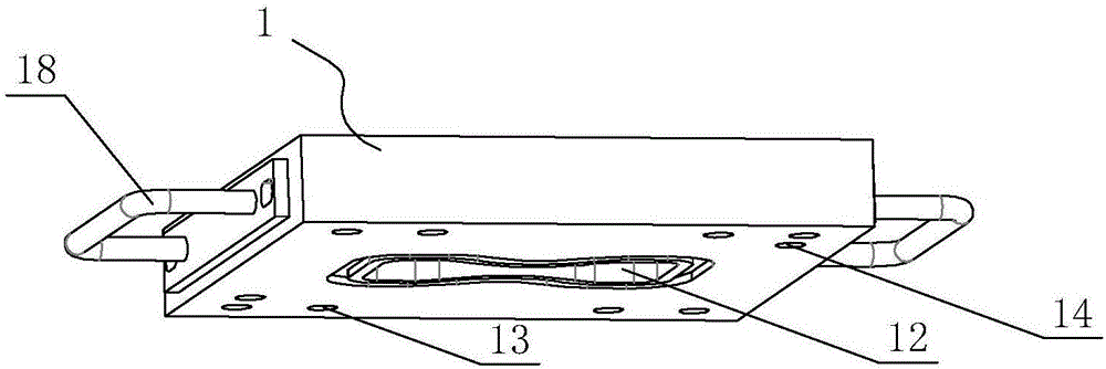
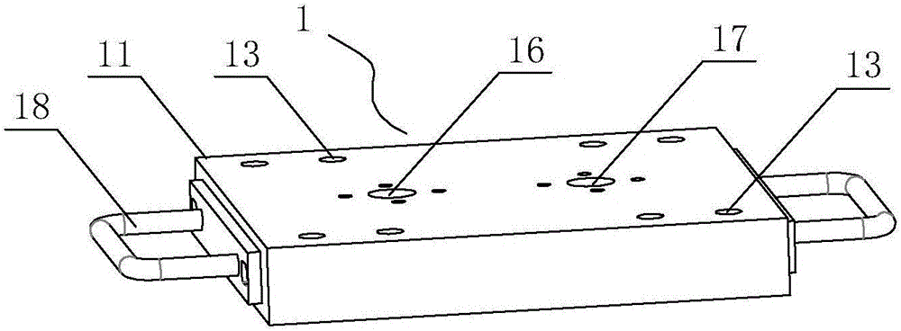
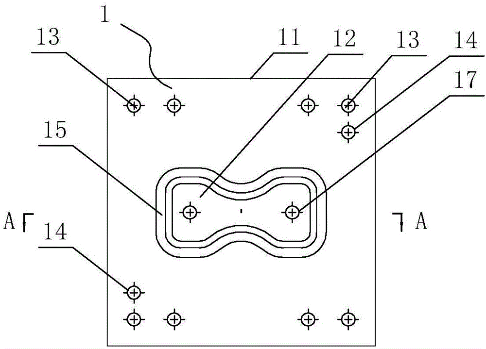
[0046] A kind of hydroforming mold, comprises upper mold 1 and lower mold 2, described lower mold is mold, upper mold is empty mold, described lower mold comprises lower mold body 21 and the lower mold cavity 22 that opens in the middle part of lower mold body, The lower mold cavity is a concave mold corresponding to the shape of the plate-shaped part to be produced (the inner cavity of the lower mold is designed to be the shape of the part to be produced), and the bottom of the lower mold cavity is provided with an air vent 25, surrounding the lower mold cavity The lower mold body has a lower locking screw hole 23 and a lower positioning pin hole 24; the upper mold 1 includes an upper mold body 11 and an upper mold cavity 12 opened in the middle of the upper mold body, and the upper mold cavity is compatible with the upper mold body. The cavity of the lower mold cavity is opposite to the mouth of the cavity, and an installation groove 15 for installing a sealing ring is provid...

Embodiment 2

[0049] A method of manufacturing complex sheet metal parts using a hydroforming die, comprising the steps of:

[0050] S1: Simulation analysis, analyzing the maximum deformation of the plate parts and the following production parameters: the pressure of the compressed liquid during forming, the lubrication coefficient between the plate and the upper die and the plate and the lower die, the forming time of the plate, springback The rate is based on the dwell time and liquid loading path corresponding to the rebound rate;

[0051] The loading path includes:

[0052] (1) Linear loading, that is, loading with equal slope of hydraulic pressure;

[0053] (2) Constant loading, that is, the loading parameter rating;

[0054] (3) Step loading, that is, the hydraulic pressure is suddenly loaded with a certain value;

[0055] S2: Open the upper and lower molds, install the sealing ring in the installation groove, place the plate with a size slightly smaller than the cross-section of the...


PUM


Abstract

A hydraulic forming die comprises an upper die body and a lower die body. The lower die body is a mold die body. The upper die body is an empty die body. An exhaust hole is formed in the bottom of a lower die cavity. An upper die cavity is provided with an oil inlet hole and an oil outlet hole. A sealing ring is arranged between the upper die cavity and the lower die cavity. An upper main die body and a lower main die body are locked through a locking bolt. A method for manufacturing a complex panel component through the hydraulic forming die comprises the steps that firstly, simulated analysis is conducted; secondly, charging and die assembly pre-tightening are conducted; thirdly, press locking is conducted; fourthly, compressed liquid is injected, and pressurizing is gradually conducted; fifthly, pressure maintaining is conducted; sixthly, pressure releasing is conducted, and the compressed liquid is discharged; and seventhly, die sinking is conduced, and the component is taken out. The die is simple in structure, short in design period and low in manufacturing cost. The middle procedures for manufacturing the complex panel component through the method are few, manpower and material resources are saved, the product thinning rate is low, and the wall thickness is uniform; the material forming extremity is high, the forming quality is good, precision is high, the bearing capability is high, and residual stress is low; and the problems that the complex panel component is prone to cracking and deformation due to drawing, and wrinkling happens to the edge pressing position are solved, and the hydraulic forming die and the method are particularly suitable for complex drawing structural pieces formed at a time.

Description

technical field [0001] The invention relates to a mold and a method for manufacturing complex plate parts with it, in particular to a hydroforming mold and a method for manufacturing complex plate parts with it. Background technique [0002] In the manufacturing industry, there are often complex-shaped plate parts with small batches and variable sizes. The traditional method of manufacturing such parts is either stamping or manual sheet metal forming; the cost of manual sheet metal forming is Low, but the cycle is too long, and the quality is not easy to meet the requirements; the stamping method also has the following problems: [0003] 1. The process is complicated, difficult, and expensive: the design, manufacture and debugging of the mold requires a lot of time, manpower and material resources. Pressing into a part requires a combination of multiple processes, a combination of multiple sets of molds, and multiple steps to stamp into qualified parts. Stamping each The p...

Claims


Application Information

Patent Timeline
Patent Type & Authority Applications(China)
IPC IPC(8): B21D26/031B21D26/027
CPCB21D26/027B21D26/031
Inventor 李健梁鹏贾宇坤苏海迪琚林锋刘邦雄辛艳峰
Owner GUANGXI UNIVERSITY OF TECHNOLOGY
Why Eureka
Try Eureka