Array type ultrasonic vibration oil well paraffin removal & control device

A technology for oil well wax removal and prevention and ultrasonic vibration, which is applied to vibration generating devices, cleaning appliances, wellbore/well components, etc., can solve the problems of complicated oil well wax removal and prevention devices, low efficiency, etc. Easy to use, enhance the effect of ultrasonic vibration intensity

Inactive Publication Date: 2017-01-25
CHINA UNIV OF PETROLEUM (EAST CHINA) +1
View PDF6 Cites 5 Cited by
  • Summary
  • Abstract
  • Description
  • Claims
  • Application Information

AI Technical Summary

Problems solved by technology

[0004] The purpose of the present invention is to provide an array type ultrasonic vibration oil well wax removal and prevention device to solve the problem of complex oil well wax removal and prevention device and low efficiency

Method used


Image

  • Array type ultrasonic vibration oil well paraffin removal & control device
  • Array type ultrasonic vibration oil well paraffin removal & control device
  • Array type ultrasonic vibration oil well paraffin removal & control device

Examples


Embodiment 1

[0022] The present invention will be further described below in conjunction with the accompanying drawings. It should be noted that this embodiment is based on the technical solution and provides detailed implementation methods and specific working processes, but the protection scope of the present invention is not limited to the present invention. Example.

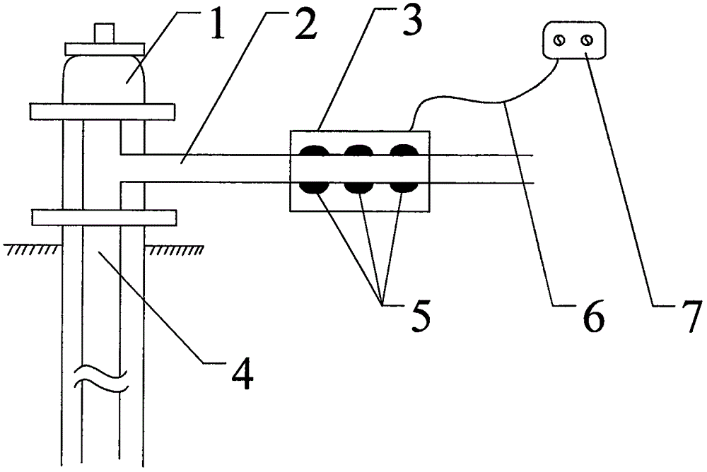
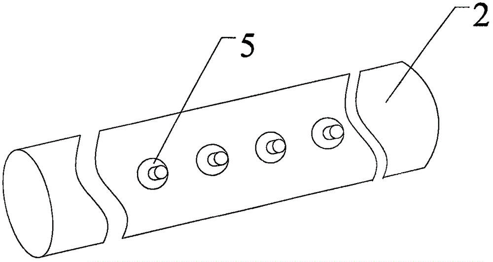
[0023] figure 1 It is a structural schematic diagram of an embodiment of the present invention, figure 2 It is a schematic diagram of the distribution of ultrasonic transducers in Embodiment 1 of the present invention. Such as figure 1 , figure 2 As shown, an array type ultrasonic vibration oil well wax removal and prevention device includes an ultrasonic signal generator 7 , an explosion-proof cable 6 , an ultrasonic transducer 5 and a protective box 3 . The ultrasonic signal transmitter 7 is connected to the ultrasonic transducer 5 through the explosion-proof cable 6, and the ultrasonic transducer 5 is fixedly con...

Embodiment 2

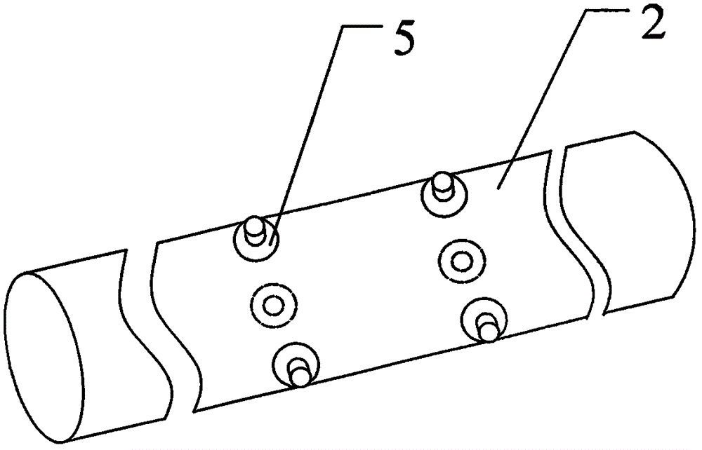
[0028] figure 1 It is a structural schematic diagram of an embodiment of the present invention, image 3 It is a schematic diagram of the distribution of ultrasonic transducers in Embodiment 2 of the present invention, Figure 4 It is a schematic cross-sectional view of the oil outlet pipe in Embodiment 2 of the present invention. Such as figure 1 , image 3 and Figure 4 As shown, an array type ultrasonic vibration oil well wax removal and prevention device includes an ultrasonic signal generator 7 , an explosion-proof cable 6 , an ultrasonic transducer 5 and a protective box 3 . The ultrasonic signal transmitter 7 is connected to the ultrasonic transducer 5 through the explosion-proof cable 6, and the ultrasonic transducer 5 is fixedly connected to the outer wall of the oil well outlet pipe 2.

[0029] In this embodiment, the ultrasonic transducers 5 are arranged in a circular array on the oil outlet pipe 2, and the distances between two adjacent ultrasonic transducers ...


PUM


Abstract

The invention discloses an array type ultrasonic vibration oil well paraffin removal & control device which comprises an ultrasonic signal generator, an explosion-proof cable, an ultrasonic transducer, and a protective housing. The array type ultrasonic vibration oil well paraffin removal & control device is characterized in that: the ultrasonic signal generator is connected with the ultrasonic transducer through the explosion-proof cable; the protective housing is arranged outside the ultrasonic transducer; the ultrasonic transducer is fixedly connected to the external wall of the outlet pipe of the oil well; distance between the ultrasonic transducers is an integral multiple of the wavelength thereof; the ultrasonic transducers are arranged in an array type on the external wall of the outlet pipe of the oil well. The array type ultrasonic vibration oil well paraffin removal & control device with the mentioned structure has the advantages of a simple structure, simple use method, good paraffin removal & control effects, and strong suitability, and can be used conveniently and effectively for paraffin removal and control in oil wells.

Description

technical field [0001] The invention belongs to the technical field of oil well wax removal and prevention equipment, and in particular relates to an array type ultrasonic vibration oil well wax removal and prevention device. Background technique [0002] In the process of oil exploitation, when the crude oil contains a certain amount of paraffin, it will inevitably form wax deposition in the production pipeline of the oil well. When the amount of wax crystals reaches a certain level, the crude oil loses its fluidity and blocks the flow channel, which stops the oil well and affects the normal production of the oil field. [0003] At present, the commonly used methods to solve wax deposition in oil wells: one is to remove and prevent wax by chemical methods. This method can better solve the problem of wax prevention in production oil wells when the chemical agent and dosage are appropriate, but the cost is high and it is not conducive to the environment. Protect. The second...

Claims


Application Information

Patent Timeline
Patent Type & Authority Applications(China)
IPC IPC(8): E21B37/00E21B28/00
CPCE21B28/00E21B37/00
Inventor 王卫阳余传谋毕伟付小波高文明焦光辉任利斌焦金生薛涛张涛王成起
Owner CHINA UNIV OF PETROLEUM (EAST CHINA)
Why Eureka
Try Eureka