Anti-expansion overlapping structure of folded plate at corner of furnace wall

A technology for connecting structures and wall corners is applied in the field of anti-expansion lap joint structures of folded plates at the corners of furnace walls, and can solve the problems that the maintenance of the thermal insulation outer shield is difficult to operate, unsightly, unable to protect the furnace wall, unable to cope with the expansion of the furnace wall, and the like. Avoid labor and material waste, avoid expansion and opening, and facilitate the realization of the effect

Active Publication Date: 2017-02-01
POWERCHINA SEPCO1 ELECTRIC POWER CONSTR CO LTD +1
View PDF7 Cites 0 Cited by
  • Summary
  • Abstract
  • Description
  • Claims
  • Application Information

AI Technical Summary

Problems solved by technology

[0002] The insulation outer guard plate at the corner of the furnace body is usually designed as a folded plate connected with the profiled plates of the furnace wall on both sides by rivets, and the nails are nailed every 0.5m in the longitudinal direction, that is, the folded plate is directly fixed to the profiled plate of the furnace wall. , although the connection is tight, it cannot cope with the expansion of the furnace wall
[0003] When the unit is running, the furnace body tends to expand laterally due to temperature rise, and the expansion stress mainly acts on the corners. The folded plates at the corners cannot cope with the expansion because they are nailed and fixedly connected to the profiled plates on both sides of the furnace wall, which can easily cause external damage. When the guard plate is pulled apart, it is neither beautiful nor able to protect the furnace wall, and it is not easy to operate when maintaining the thermal insulation outer guard plate, and the maintenance process is very cumbersome

Method used


Image

  • Anti-expansion overlapping structure of folded plate at corner of furnace wall

Examples


Embodiment Construction

[0024] The present invention will be further described below in conjunction with the accompanying drawings and embodiments.

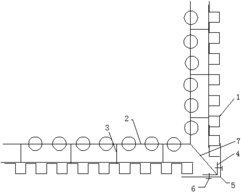
[0025] Such as figure 1 As shown, the anti-expansion overlapping structure of the folded plate at the corner of the furnace wall includes the thermal insulation outer guard plate 1, and there is a set gap between the thermal insulation outer guard plate 1 and the furnace wall profiled plate 2, and the thermal insulation outer guard plate The templates 2 are connected by a plurality of connectors 3, the connectors 3 have a set distance, the corners of the profiled plates 2 of the furnace wall are connected with the support 4, and the support 4 is fixedly connected with the limit plate. Connector 3 can be selected from flat steel.

[0026] The limit plate is a right-angle folded plate 5, and its end extends to the outer surface of the adjacent thermal insulation outer guard plate 1, so that the limit plate is arranged parallel to the outer surface of the...


PUM


Abstract

The invention discloses an anti-expansion overlapping structure of a folded plate at a corner of a furnace wall. The anti-expansion overlapping structure comprises external thermal-insulation protective plates. Set clearances exist between the external thermal-insulation protective plates and furnace wall pressure plates; and the external thermal-insulation protective plates are connected with the corresponding furnace wall pressure plates through a plurality of connecting bodies, and set distances exist between the connecting bodies. The corners of the furnace wall pressure plates are connected with a supporting piece which is fixedly connected with limiting plates. The ends of the limiting plates extend into the outer surfaces of the adjacent external thermal-insulation protective plates, so that the limiting plates are made parallel to the outer surfaces of the adjacent external thermal-insulation protective plates, set clearances exist between the limiting plates and the outer surfaces of the adjacent external thermal-insulation protective plates, and the limiting plates and the outer surfaces of the adjacent external thermal-insulation protective plates are arranged alternately in the vertical direction or the horizontal direction. Screw-free overlapping is adopted between the folded plate at the corner and the furnace wall pressure plates on the two sides, the right-angled folded plate is directly fixed to the supporting piece, certain deformation allowance is provided for the protective plate, and expansion and pulling-open of the protective plate are effectively avoided.

Description

technical field [0001] The invention relates to an anti-expansion overlapping joint structure of a folded plate at the corner of a furnace wall. Background technique [0002] The insulation outer guard plate at the corner of the furnace body is usually designed as a folded plate connected with the profiled plates of the furnace wall on both sides by rivets, and the nails are nailed every 0.5m in the longitudinal direction, that is, the folded plate is directly fixed to the profiled plate of the furnace wall. , although the connection is tight, it cannot cope with the expansion of the furnace wall. [0003] When the unit is running, the furnace body tends to expand laterally due to temperature rise, and the expansion stress mainly acts on the corners. The folded plates at the corners cannot cope with the expansion because they are nailed and fixedly connected to the profiled plates on both sides of the furnace wall, which can easily cause external damage. When the guard plat...

Claims


Application Information

Patent Timeline
Patent Type & Authority Applications(China)
IPC IPC(8): F23M5/00
CPCF23M5/00F23M2900/05002
Inventor 朱北平郑旭豪王海涛
Owner POWERCHINA SEPCO1 ELECTRIC POWER CONSTR CO LTD
Why Eureka
Try Eureka