
Metering circuit for multichannel AC digital electric energy meter
A digital electric energy meter and measurement circuit technology, applied in the measurement of electrical variables, measurement devices, instruments, etc., can solve the problems of low acquisition and measurement accuracy, and the inability of smart meters to voltage and current data, so as to improve measurement accuracy and power conversion. efficiency and improve power supply stability
- Summary
- Abstract
- Description
- Claims
- Application Information
AI Technical Summary
Problems solved by technology
Method used
Image

Examples
Embodiment Construction
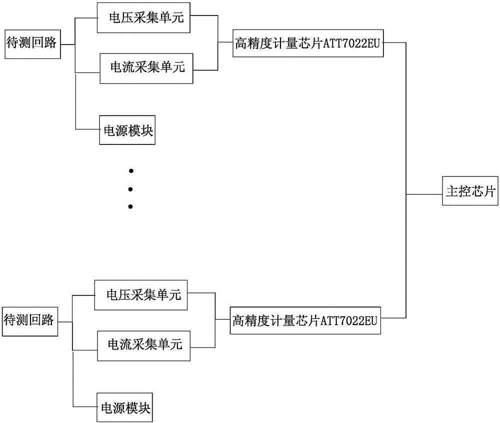
[0046] Such as figure 1 As shown, a metering circuit applied to a multi-channel AC digital watt-hour meter, the input end is connected to the circuit to be tested, the output end is connected to the data input end of the main control chip, the control end is connected to the chip selection terminal of the main control chip, and Power supply module connection, including 12-channel voltage acquisition unit, 12-channel current acquisition unit and four metering chips. The current signal of the loop to be tested is connected to the input end of each metering chip with the output end of the three-way voltage acquisition unit and the output end of the three-way current acquisition unit respectively.
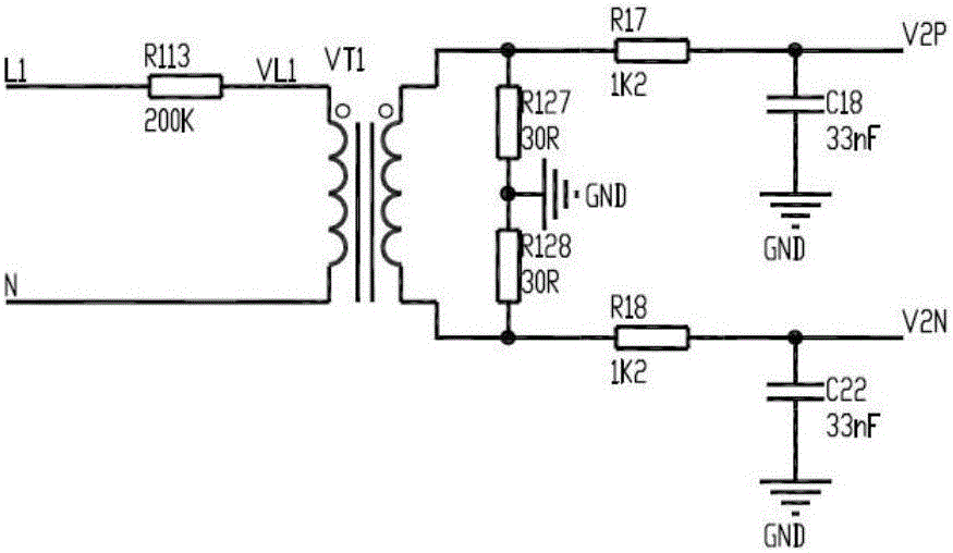
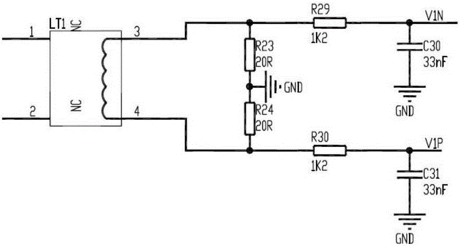
[0047] Such as figure 2 As shown, the voltage acquisition unit includes a voltage transformer, the input terminal of the voltage transformer is connected to a circuit to be tested, one output terminal of the voltage transformer is connected to the resistor R127 and grounded, and the ...
PUM
 Abstract
Description
Claims
Application Information