Substrate integrated waveguide leaky-wave antenna with big circular polarization beam scanning range

A substrate-integrated waveguide and beam scanning technology, applied to leaky waveguide antennas, circuits, etc., to achieve the effects of easy design optimization, simple structure, and large circularly polarized beam scanning range

Active Publication Date: 2017-04-19
HARBIN INST OF TECH
View PDF3 Cites 27 Cited by
  • Summary
  • Abstract
  • Description
  • Claims
  • Application Information

AI Technical Summary

Problems solved by technology

However, the circularly polarized beam scanning range of this kind of antenna is only within ±15°

Method used


Image

  • Substrate integrated waveguide leaky-wave antenna with big circular polarization beam scanning range
  • Substrate integrated waveguide leaky-wave antenna with big circular polarization beam scanning range
  • Substrate integrated waveguide leaky-wave antenna with big circular polarization beam scanning range

Examples


specific Embodiment approach 1

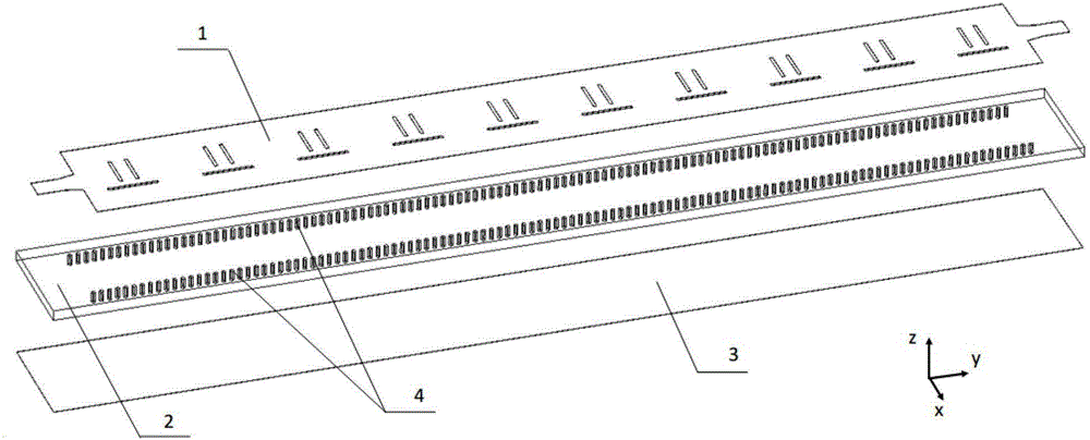
[0031] Specific implementation mode one: the following combination Figure 2 to Figure 5 This embodiment will be described. Depend on figure 2 , the circularly polarized substrate integrated waveguide leaky wave antenna described in this embodiment, its main structure can be divided into three layers - the top metal layer 1, the dielectric substrate layer 2, the bottom metal layer 3 and the double row of metallized via holes 4 ;

[0032] The top metal layer 1 and the bottom metal layer 3 are on the upper and lower sides of the dielectric substrate layer 2, and the three are tightly combined into one body by hot pressing;

[0033] The material of the dielectric substrate layer 2 is a typical microwave plate, the dielectric constant εr is between 2 and 10, and the loss tangent tanδ<0.01;

[0034] Double rows of metallized vias 4 penetrate the dielectric substrate 2, and are metallized by electroplating, so that the top metal layer 1 and the bottom metal layer 3 are electrica...

specific Embodiment approach 2

[0044] Specific implementation mode two: the following combination Figure 6 to Figure 9 This implementation mode is described, and the antenna structure of the first implementation mode is further described in this implementation mode in combination with specific examples.

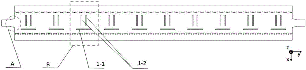
[0045] As a special case, Image 6 and Figure 7 The specific design parameters of a circularly polarized substrate-integrated waveguide leaky-wave antenna operating from 10GHz to 14.5GHz are given. Depend on Image 6 , the top dielectric plate of the antenna is a microwave substrate, and the relative permittivity ε r =3.66, loss tangent tanδ=0.004, thickness ts=0.762mm, metal layer thickness tm=0.035mm. The antenna is composed of N=10 periodic slot units, unit spacing p=14mm, longitudinal slot 1-1 length L=7mm, transverse slot pair 1-2 length T=5.4mm, longitudinal slot 1-1 and transverse slot pair 1 The width of -2 is ws=0.4mm, the slot distance dy=2.4mm in the transverse slot pair 1-2, the distance...


PUM

PropertyMeasurementUnit
Thicknessaaaaaaaaaa
Thicknessaaaaaaaaaa
Thicknessaaaaaaaaaa

Abstract

The invention discloses a substrate integrated waveguide leaky-wave antenna with a big circular polarization beam scanning range, belongs to the field of microwave antenna engineering, and solves a problem that a conventional circular polarization leaky-wave antenna is small in circular polarization beam scanning range. The antenna is of a three-layer structure, wherein the top and the bottom are metal layers, and the central part is a dielectric base material layer. The top metal layer and the bottom metal layer are electrically connected through two rows of metalized via holes, and the top metal layer forms a microstrip, a substrate integrated waveguide converter and N antenna units through etching. Each antenna unit comprises one longitudinal seam and a pair of lateral seams, and the longitudinal seam and the lateral seam pair respectively provide the loading of parallel capacitance and series inductance, can achieve the inhibition of the stop band of the leaky-wave antenna, and achieve the backward, lateral and forwarding continuous scanning of a beam. The longitudinal seam and the lateral seam pair also respectively provide independent controllable lateral polarization and longitudinal polarization radiation, thereby achieving the big circular polarization beam scanning range.

Description

technical field [0001] The invention belongs to the technical field of microwave antenna engineering. It can be widely used in modern wireless mobile communication, satellite communication in motion and various radar systems. Background technique [0002] Leaky-wave antennas are a type of traveling-wave antennas that radiate by introducing radiating elements on the transmission line to excite specific fast-wave modes. The leaky wave antenna has the unique property that the beam changes with frequency. Compared with the array antenna that can realize similar functions, it has excellent characteristics such as high directivity and simple feeding structure. Therefore, since W.W.Hansen proposed in the 1940s, the leaky wave antenna Wave antennas have always been a research hotspot in the field of antennas. The original leaky-wave antenna was composed of slotted rectangular waveguide. In recent years, with the rapid development of substrate-integrated waveguide technology, leaky...

Claims


Application Information

Patent Timeline
IPC IPC(8): H01Q13/20
Inventor 孟繁义吕玥珑于赫
Owner HARBIN INST OF TECH
Why Eureka
Try Eureka