
A Buckling Induced Brace with Two-way Helical Induced Units at the End
A two-way helix and sub-unit technology, applied in building types, buildings, building components, etc., can solve problems such as low design flexibility, unfavorable plastic hinges, etc., to simplify the manufacturing process, good axial bearing capacity, and avoid the overall destabilizing effect
- Summary
- Abstract
- Description
- Claims
- Application Information
AI Technical Summary
Problems solved by technology
Method used
Image

Examples
Embodiment Construction
[0024] The present invention will be further described below in conjunction with the accompanying drawings.
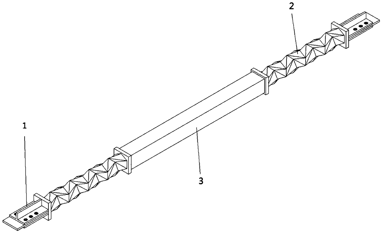
[0025] figure 1 It is a structural schematic diagram of a buckling-induced brace with a bidirectional helical induction element at the end, which is composed of an end restraint section 1, an energy dissipation section 2 and a brace straight section 3, and the end restraint section 1 is fixed at the beam-column node and the energy dissipation section 2, the energy dissipation section 2 is fixed at both ends of the supporting straight section 3.
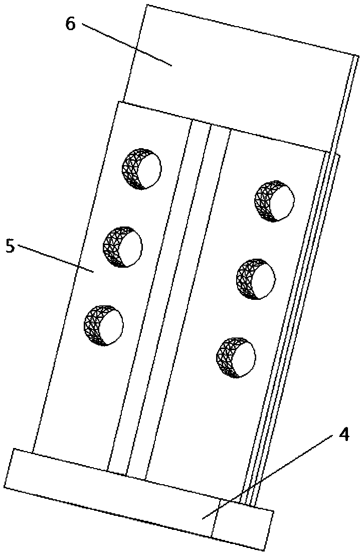
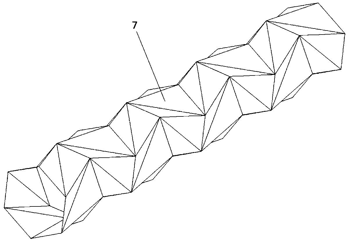
[0026] Such as figure 2 As shown, the end restraint section 1 is composed of a square steel plate 4, a T-shaped short steel beam 5, and a connecting plate 6 reserved for components such as beams and columns. The square steel plate 4 is welded to the end of the energy dissipation section 2. Two T-shaped short steel The beam 5 is welded to the square steel plate 4, and the square steel plate 4 and the T-shaped short steel bea...
PUM
 Abstract
Description
Claims
Application Information