Imaging method and system used in video monitoring

An imaging method and video monitoring technology, applied in closed-circuit television systems, image data processing, 3D modeling, etc., can solve problems such as repeated construction of 3D display data, reduce display time, solve repeated construction of 3D display data, and improve calculation speed effect

Active Publication Date: 2017-05-17
HANGZHOU HIKVISION DIGITAL TECH
View PDF6 Cites 9 Cited by
  • Summary
  • Abstract
  • Description
  • Claims
  • Application Information

AI Technical Summary

Problems solved by technology

[0009] The purpose of the present invention is to provide an imaging method and system for video monitoring. The present invention can improve the calculation speed and reduce the display time by spatially dividing and optimizing the display data, and at the same time solve the problem of repeatedly constructing three-dimensional display data

Method used


Image

  • Imaging method and system used in video monitoring
  • Imaging method and system used in video monitoring
  • Imaging method and system used in video monitoring

Examples


Embodiment Construction

[0042]In order to make the object, technical solution and advantages of the present invention clearer, the present invention will be further described in detail below in combination with specific embodiments and with reference to the accompanying drawings. It should be understood that these descriptions are exemplary only, and are not intended to limit the scope of the present invention. Also, in the following description, descriptions of well-known structures and techniques are omitted to avoid unnecessarily obscuring the concept of the present invention.

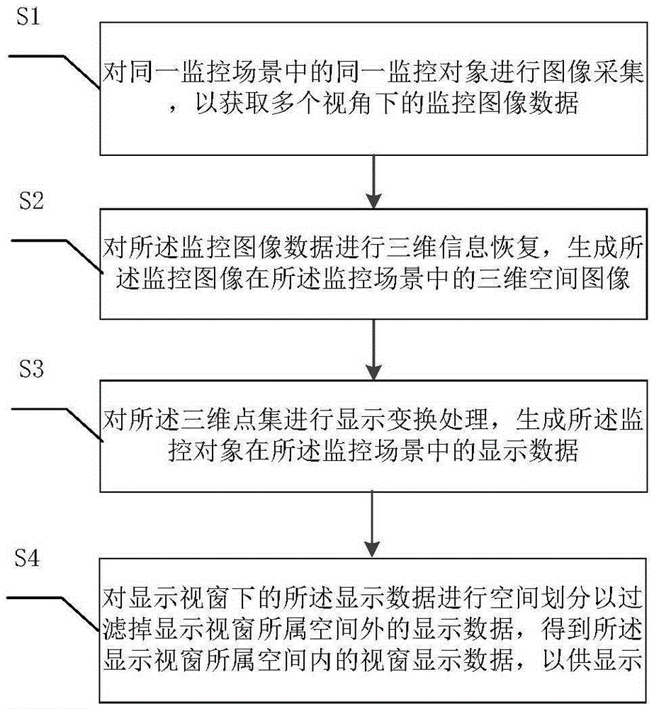
[0043] figure 1 is a flow chart of the imaging method for video surveillance according to the embodiment of the present invention.

[0044] Such as figure 1 As shown, the present invention provides a kind of imaging method of video monitoring, and described method comprises the steps:

[0045] Step S1, image acquisition is performed on the same monitoring object in the same monitoring scene, and monitoring image data fr...


PUM


Abstract

The invention discloses an imaging method and system used in video monitoring. The method includes the following steps: acquiring images of the same to-be-monitored object in the same monitoring scenario to obtain monitoring image data under a plurality of viewing angles; conducting 3D information recovery on the monitoring image data, generating a 3D spatial image of the to-be-monitored object in the monitoring scenario, wherein the 3D spatial image includes a 3D point set including 3D spatial position information; conducting display converting processing on the 3D point set, generating display data of the to-be-monitored object in the monitoring scenario; conducting space partitioning on the display data in a display window so as to filter display data beyond the space of the display window, obtaining display window data within the space of the display window. According to the invention, the method and the system, by conducting space partitioning and optimization on the display data, can increase computing speed and reduce display time, and also addresses the problem of repetitive construction of the 3D display data.

Description

technical field [0001] The invention relates to the technical field of video surveillance, in particular to an imaging method and system for video surveillance. Background technique [0002] The virtual representation of the three-dimensional monitoring object is based on the key analysis of various performances or characteristics of the computer, and the obtained low-dimensional signal is processed and expressed as a graphic image with certain three-dimensional spatial position information, which is reconstructed by means of various depth restoration algorithms 3D spatial information. [0003] Traditional 3D modeling methods can be divided into two categories: [0004] The first category is to manually carry out three-dimensional geometric modeling through computer software, for example, by means of computer graphics software. [0005] The second type is to use the obtained low-dimensional signal, process it and express it as a graph or image with certain three-dimensiona...

Claims


Application Information

Patent Timeline
Patent Type & Authority Applications(China)
IPC IPC(8): G06T17/00H04N7/18
CPCG06T17/00H04N7/18
Inventor 许爱秋汪渭春
Owner HANGZHOU HIKVISION DIGITAL TECH
Why Eureka
Try Eureka