Horn-shaped antenna transmitting and emitting RF signals in different frequency ranges

A frequency band radio frequency, horn-shaped technology, which is applied in the field of transmitting devices, can solve the problems that the antenna cannot achieve structural integration and cannot transmit radio frequency signals at the same time, and achieves the effects of simple structure, reduced radiation loss, and easy processing.

Inactive Publication Date: 2017-07-07
10TH RES INST OF CETC
View PDF3 Cites 1 Cited by
  • Summary
  • Abstract
  • Description
  • Claims
  • Application Information

AI Technical Summary

Problems solved by technology

[0006] The purpose of the present invention is to solve the problem that the current radio frequency transmission line cannot transmit radio frequency signals of different frequency bands at the same time, and cannot realize structural integration with the antenna, and provides a simple structure, easy processing and realization, high electromagnetic energy shielding degree, and strong shielding characteristics

Method used


Image

  • Horn-shaped antenna transmitting and emitting RF signals in different frequency ranges
  • Horn-shaped antenna transmitting and emitting RF signals in different frequency ranges

Examples


Embodiment Construction

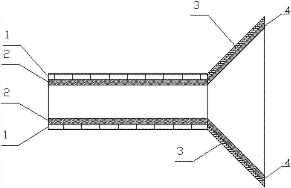
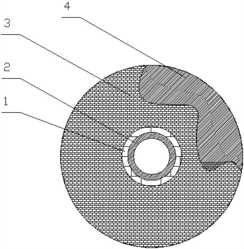
[0016] refer to figure 1 . In the embodiment described below, a horn antenna for transmitting and emitting radio frequency signals in different frequency bands includes: an outer dielectric layer 1 , a metal layer 2 and a metal horn body 4 . The metal layer 2 is made of a hollow cavity, and the outer dielectric layer 1 is connected to the metal layer 2. In the longitudinal direction, the outer dielectric layer 1 and the metal layer 2 are coaxially fixed on the small end of the metal horn body 4. The outer dielectric layer 1 The horn dielectric layer 3 is formed by extending the small port of the tapered horn along the tapered surface of the metal horn body 4; the radio frequency signals of different frequency bands pass through the dielectric body area of ​​the outer dielectric layer 1 and the conductor cavity of the metal layer 2 respectively, and are simultaneously transmitted to the tapered The small port of the horn transmits radio frequency signals of different frequency...


PUM


Abstract

The invention provides a horn-shaped antenna transmitting and emitting RF signals in different frequency ranges, and aims at providing an emitter which is simple in structure, easy to process and capable of transmitting the RF signals in different frequency ranges simultaneously. The internal of an external dielectric layer (1) is connected with a metal layer (2), the external dielectric layer and the metal layer are coaxially fixed to the small end of a tapered horn of a metal horn body (4) in the vertical direction, and the external dielectric layer extends along the tapered surface of the metal horn body (4) via a small-end port of the tapered horn to form a horn dielectric layer (3); and the RF signals in different frequency ranges are transmitted to the small-end port of the tapered horn simultaneously via a dielectric body area of the external dielectric layer (1) and a conductor cavity of the metal layer (2) respectively, and are emitted via a dielectric area of the horn dielectric layer (3) and a conductor cavity of the metal horn body (4). According to the horn-shaped antenna, the problem that an RF signal waveguide structure capable of transmitting RF signals in the same frequency range cannot be structurally integrated with the antenna is solved.

Description

technical field [0001] The invention relates to a transmitting device capable of realizing simultaneous transmission and emission of multi-band radio frequency signals, and realizing structural integration of a transmission line and an antenna. Background technique [0002] The antennas used by the base station are divided into transmitting antennas and receiving antennas, and can be divided into omnidirectional and directional. Generally, there are three configuration methods: omnidirectional transmission and omnidirectional reception; omnidirectional transmission and directional reception; directional transmission, Receive orientation. It can be understood literally that each method is different. Sending omnidirectional is mainly responsible for all-round signal transmission; receiving omnidirectional is naturally the reception of azimuth signals; directional means only sending and receiving at a fixed angle. In general, base stations with fewer channels (such as located ...

Claims


Application Information

Patent Timeline
Patent Type & Authority Applications(China)
IPC IPC(8): H01Q13/02H01Q1/36H01Q1/50H01Q1/52H01Q5/307
CPCH01Q13/02H01Q1/36H01Q1/50H01Q1/526H01Q5/307
Inventor 王志辉
Owner 10TH RES INST OF CETC
Why Eureka
Try Eureka