AI technical title is built by Patsnap AI team. It summarizes the technical point description of the patent document.
A technology of installation structure and lock cylinder, applied in the application of locks, building locks, vehicle locks, etc., can solve problems such as door opening, and achieve the effect of preventing the removal of the lock cylinder
Active Publication Date: 2020-04-28
U SHIN LTD
View PDF6 Cites 0 Cited by
Summary
Abstract
Description
Claims
Application Information
AI Technical Summary
This helps you quickly interpret patents by identifying the three key elements:
Problems solved by technology
Method used
Benefits of technology
Problems solved by technology
[0003] In this type of lock cylinder installation structure, since only one screw is used for assembly, a person who wants to pick the lock may destroy the peripheral part of the installation screw, especially the resin base member, etc., and then remove the lock cylinder. open the car door
Method used
Image
Click on the blue label to locate the original text in one second.
Reading with bidirectional positioning of images and text.
Examples
no. 1 approach
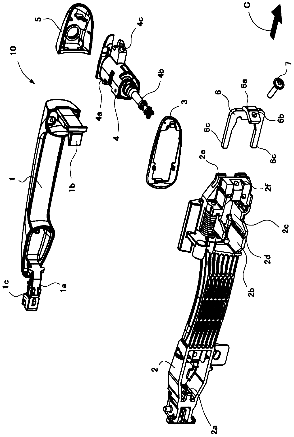
[0069] figure 1 It is a figure which shows 1st Embodiment of the door handle apparatus 10 which employ|adopts the mounting structure of the key cylinder of this invention.
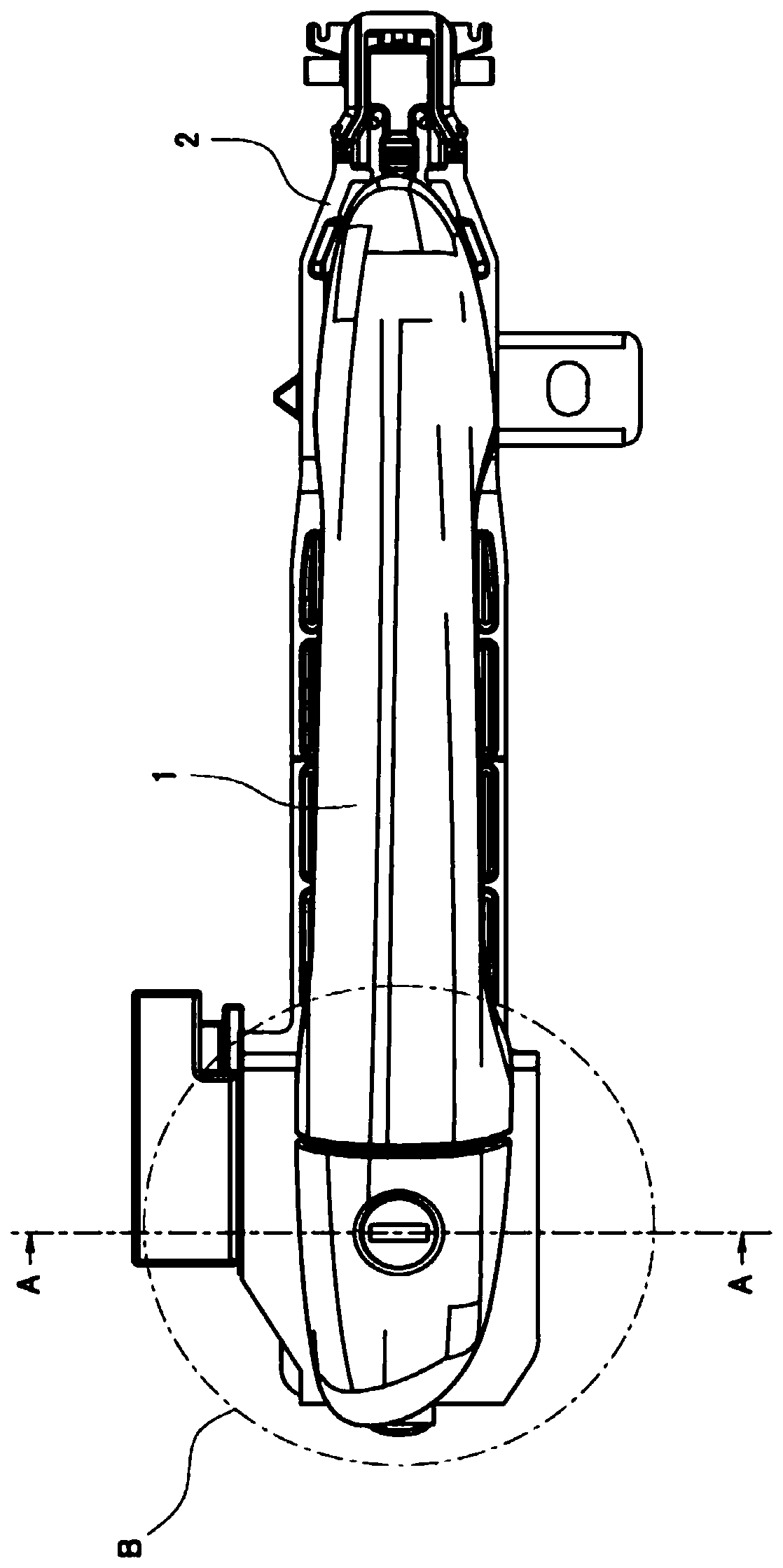
[0070] figure 2 It is a figure which looked at the door handle apparatus 10 from the vehicle outer side.
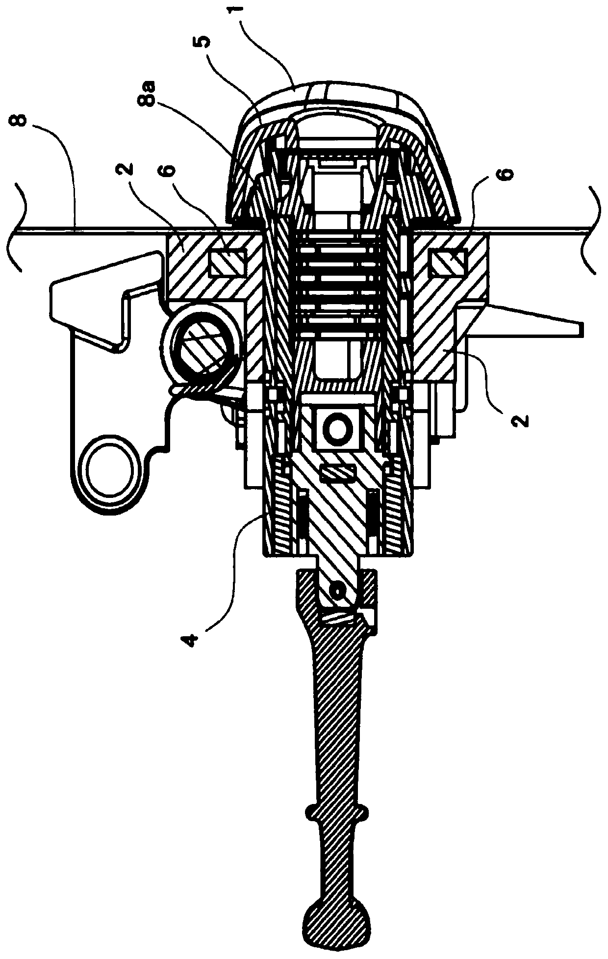
[0071] image 3 is in figure 2 A cross-sectional view cut at the position indicated by the arrow A-A in .
[0072] Additionally, include Figure 1 to Figure 3 , the figures shown below are all schematic diagrams, and the size and shape of each part are appropriately exaggerated for easy understanding.
[0073] In addition, although specific numerical values, shapes, materials, etc. are demonstrated below, these can be changed suitably.
[0074] In addition, in the following description, the outer side of a vehicle is called a surface, and the inner side of a vehicle is called a rear side.
[0075] Such as Figure 1 to Figure 3 As shown, the door handle device 10 of this embodiment is mounte...
no. 2 approach
[0121] Figure 10 It is a figure which shows the 2nd Embodiment of the door handle apparatus 10 which employ|adopts the mounting structure of the key cylinder of this invention.
[0122] Figure 11 It is a figure which looked at the door handle apparatus 10 from the vehicle outer side.
[0123] Figure 12 is in Figure 11 A cross-sectional view cut at the position indicated by the arrow A-A in .
[0124] Additionally, include Figure 10 to Figure 12 , the figures shown below are schematic diagrams, and the size and shape of each part are appropriately exaggerated for easy understanding.
[0125] In addition, in the following description, although specific numerical values, shapes, materials, etc. are demonstrated, these can be changed suitably.
[0126] In addition, in the following description, the outer side of a vehicle is called a front side, and the inner side of a vehicle is called a rear side, and it demonstrates.
[0127] Such as Figure 10 to Figure 12 As show...
PUM
Abstract
The invention provides a mounting structure of a key cylinder, the periphery of screw mounting portion is hard to damage, detaching the key cylinder can be avoided even if the periphery of screw mounting portion is damaged. The mounting structure of a key cylinder in a door handle device (10) comprises: a substrate component through part (2f) arranged on a substrate component (2), the key cylinder (4) inserting to a key cylinder inserting part (2c) from the outside of a vehicle via a mounting hole (8a) formed by a door sheet (8), a screw mounting part (4c) arranged on the key cylinder (4), a mounting screw (7) screwed into the screw mounting part (4c) of the key cylinder (4) via the substrate component through part (2f) to fix the key cylinder (4) to the substrate component (2), and a protection component (6) which comprises a screw through part (6b) for the mounting screw (7) and is fixed to the periphery of the key cylinder inserting part (2c) of the key cylinder (4) in the substrate component (2) through the mounting screw (7) of the screw through part (6b) to protect the substrate component (2) on the periphery of the key cylinder inserting part (2c).
Description
technical field [0001] The invention relates to an installation structure of a lock cylinder. Background technique [0002] The lock cylinder that is arranged on the outer handle of the automobile, for example, that of Patent Document 1 Figure 7 As described above, an insertion hole for the handle is provided on the base member fixed to the inner surface side of the door panel, and the lock cylinder is inserted into the installation hole communicated with the insertion hole. And, the lock cylinder is fixed on the base member by screwing the screw passing through the base member into the screw hole formed on the shell of the lock cylinder. [0003] In this type of lock cylinder installation structure, since only one screw is used for assembly, a person who wants to pick the lock may destroy the peripheral part of the installation screw, especially the resin base member, etc., and then remove the lock cylinder. Open the car door. [0004] prior art literature [0005] Pate...
Claims
Application Information
Patent Timeline
Application Date:The date an application was filed.
Publication Date:The date a patent or application was officially published.
First Publication Date:The earliest publication date of a patent with the same application number.
Issue Date:Publication date of the patent grant document.
PCT Entry Date:The Entry date of PCT National Phase.
Estimated Expiry Date:The statutory expiry date of a patent right according to the Patent Law, and it is the longest term of protection that the patent right can achieve without the termination of the patent right due to other reasons(Term extension factor has been taken into account ).
Invalid Date:Actual expiry date is based on effective date or publication date of legal transaction data of invalid patent.

