Power electronic transformer

A technology of power electronics and transformers, applied in the field of electrified railway traction power supply, to achieve the effect of energy feedback, two-way flow, and improvement of power quality

CN107104443AActive Publication Date: 2017-08-29SOUTHWEST JIAOTONG UNIV
17 Cites 11 Cited by

Patent Information

Authority / Receiving Office
CN · China
Patent Type
Applications(China)
Current Assignee / Owner
Publication Date
2017-08-29

Smart Images

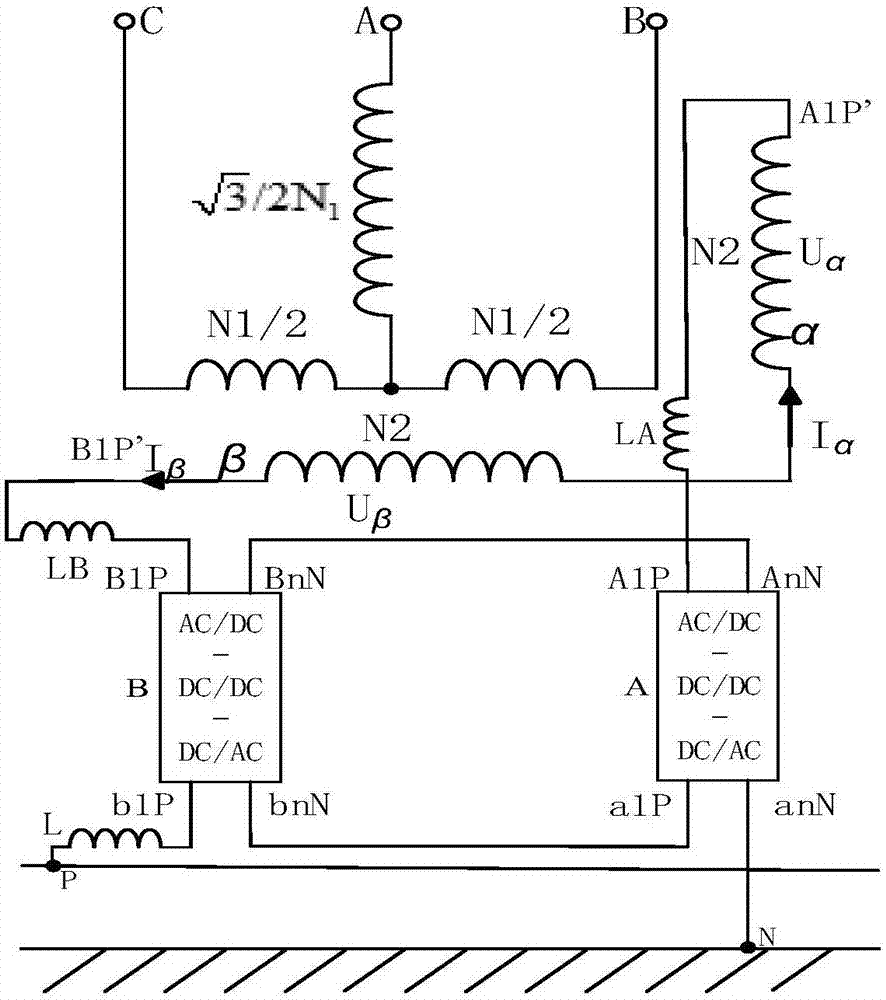
  • Figure 1
    Figure 1
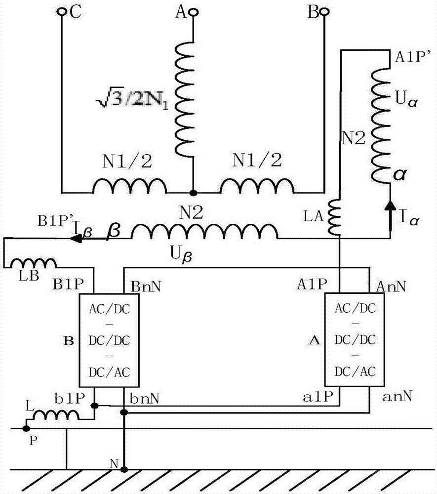
  • Figure 2
    Figure 2
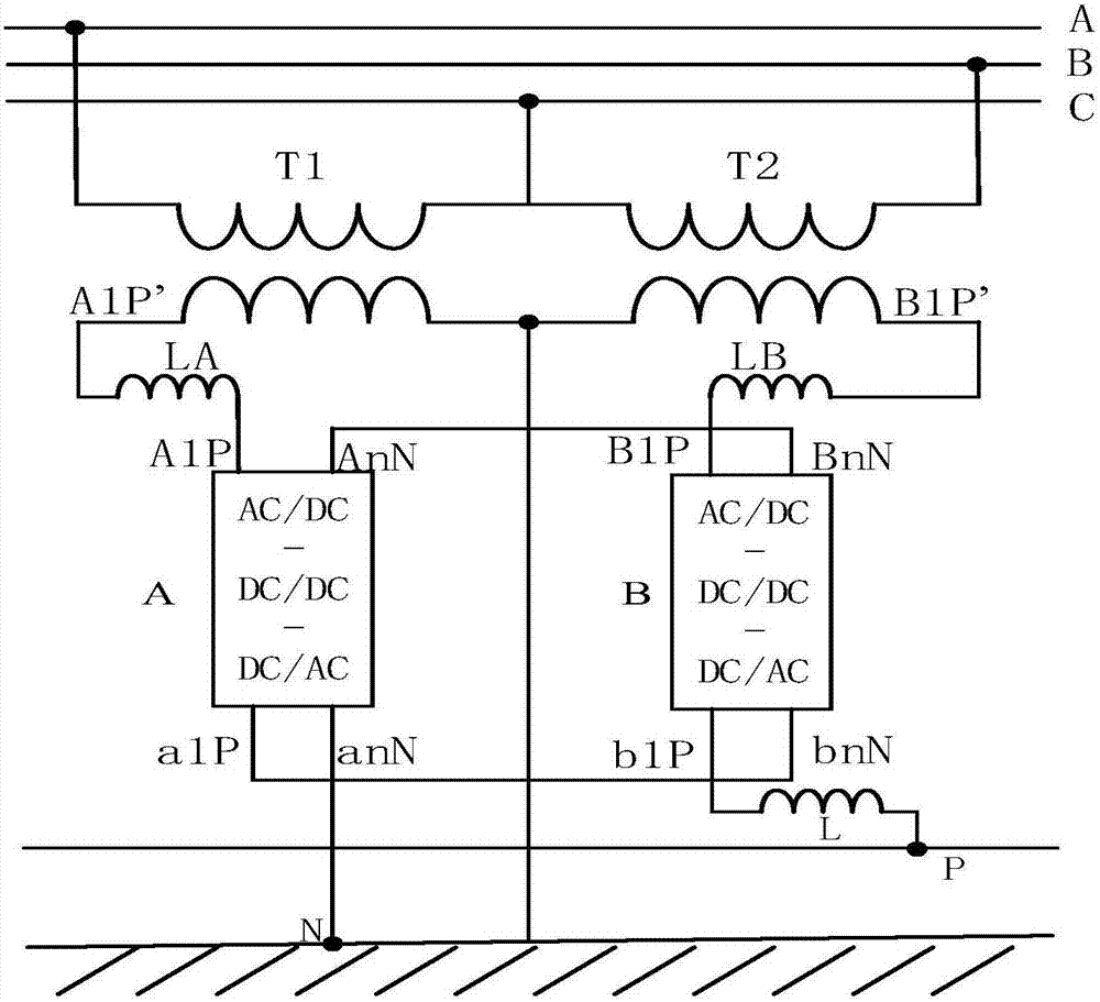
  • Figure 3
    Figure 3
Patent Text Reader

Abstract

The invention provides a power electronic transformer, relates to the technical field of electrified railway traction power supply, and solves the problems of dynamically controlling negative-sequence current, compensating reactive power and electrical sectioning of a traction network. The power electronic transformer is an input cascade structure two phase-single phase power electronic transformer, which is formed by cascading n converter modules; when the power electronic transformer is cooperated with a Scott transformer, an alpha phase output A1P' is connected with a positive input end A1P of a single-phase power electronic transformer A by a linking reactor LA; a beta phase output B1P' is connected with a positive input end B1P of a single-phase power electronic transformer B by a linking reactor LB; a negative input end AnN of the transformer A is connected with a negative input end BnN of the transformer B; when a parallel output structure is used, a positive output end a1P of the transformer A is connected with the positive output end b1P of the transformer B; the negative output end anN of the transformer A is connected with the negative output end bnN of the transformer B; the negative output end anN of the single-phase power electronic transformer A is connected with a rail; and, the positive output end b1P of the transformer B is connected with a contact system by the reactor.
Need to check novelty before this filing date? Find Prior Art

Description

technical field

[0001] The invention relates to the technical field of electric railway traction power supply. Background technique

[0002] At present, there are a large number of single-phase loads in China, especially the traction power supply system in my country. The electrified railway adopts single-phase power frequency AC system. The traction power supply system is connected to the power system through the traction substation. The core equipment of the traction substation is Traction transformer. In recent years, traction transformers with Vv wiring in direct supply mode, traction transformers with Vx wiring in AT mode, Ynvd traction transformers, Scott (Scott) traction transformers, etc. have realized three-phase-two-phase conversion, but the traction power supply system in my country There are two main problems: electricity split phase problem, negative sequence problem. The problem of electric phase separation makes the power supply line have no electricity area, ...

Examples

specific Embodiment approach

[0021] figure 1 , 2 Shown is the output series and output parallel external wiring modes used in conjunction with the Scott (Scott) traction transformer of the present invention. image 3 , 4 Shown is the situation that the present invention is used in conjunction with the Vv connection transformer. Figure 5 , Image 6 Shown are the internal specific implementations of the output parallel connection and output series connection of the present invention: a two-phase-single-phase power electronic transformer, including a traction transformer, a single-phase power electronic transformer A and a single-phase power electronic transformer B. It is suitable for two-phase-single-phase power electronic transformers in traction substations. On the basis of existing substations, each phase (A, B, C) of the three-phase grid outputs α(T1), β through the traction transformer (T2) Two-phase, and then cascaded n (n>1) converter modules (A1-An, B1-Bn) connected to form a conversion device...