Jaw clutch

A jaw clutch, clutch technology, applied in clutches, fluid drive clutches, mechanical drive clutches, etc., can solve problems such as affecting measurement accuracy

Active Publication Date: 2017-08-29
ZF FRIEDRICHSHAFEN AG
View PDF6 Cites 5 Cited by
  • Summary
  • Abstract
  • Description
  • Claims
  • Application Information

AI Technical Summary

Problems solved by technology

The disadvantage of this embodiment is that the sensor and the sensor element are installed outside the switching clutch or outside the differential drive, so that they are exposed to adverse environmental influences that affect the accuracy of the measurement.

Method used


Image

  • Jaw clutch
  • Jaw clutch
  • Jaw clutch

Examples


Embodiment Construction

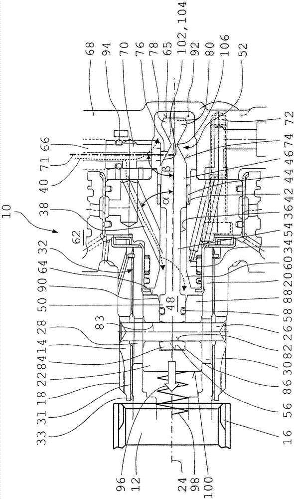
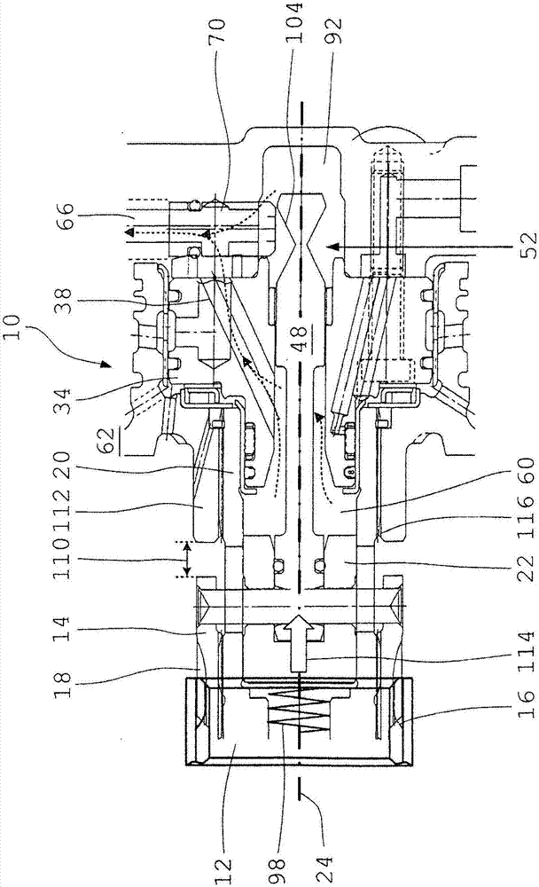
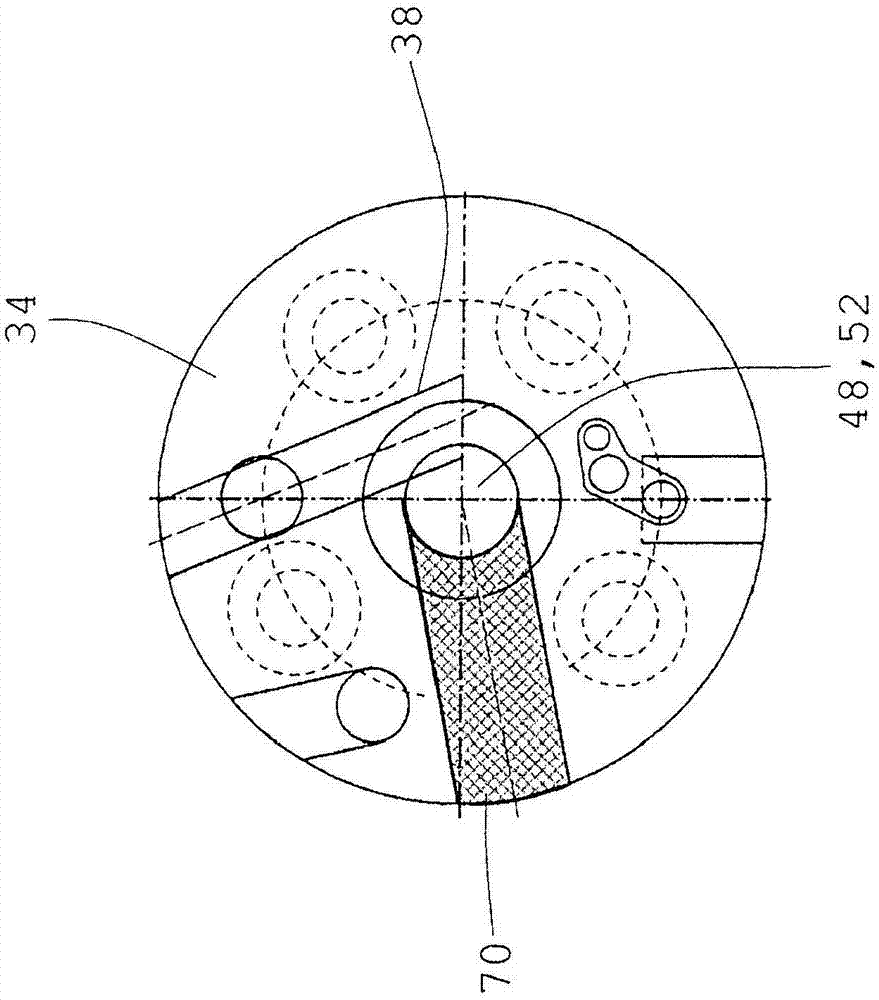
[0030] exist Figures 1 to 3 The jaw clutch 10 shown in FIG. 1 has a fixed clutch part 12 and an axially movable clutch part 14 . The two clutch parts 12 , 14 are each substantially hollow-cylindrical, wherein the fixed clutch part 12 has an axial inner toothing 16 and the axially movable clutch part 14 has an axial outer toothing 18 . , the teeth of the inner tooth part and the outer tooth part cooperate with the tooth slots of the corresponding other tooth part. The two clutch parts 12 , 14 are arranged coaxially with one another, so that the movable clutch part 14 , which is smaller in diameter, is partially displaceable in the axial direction into the fixed clutch part 12 . This results in a form-locking connection which enables a torque transmission between the two clutch parts 12 , 14 .

[0031] For actuating the dog clutch 10 , it also has an approximately hollow-cylindrical cylinder housing 20 in which a pot-shaped piston 22 is accommodated so as to be displaceable c...


PUM


Abstract

The invention relates to a jaw clutch (10) having an axially static clutch part (12) and having an axially movable clutch part (14), wherein the axially static clutch part (12) and the axially movable clutch part (14) are of sleeve-shaped form and are arranged coaxially with respect to one another, wherein the axially movable clutch part (14) can, in order to produce a positively locking connection to the axially static clutch part (12), be displaced axially by way of a piston (22) that can be actuated by pressure medium, wherein the piston (22) is arranged in longitudinally displaceable fashion in a cylinder housing (20) which, radially on the outside, bears the axially movable clutch part (14), wherein the piston (22) is connected by way of a piston pin (26) to the axially movable clutch part (14), and wherein pressure medium (40) can be supplied to the cylinder chamber (60) of the cylinder housing (20) via a supply duct (38), the piston (22) being fixedly connected, at one axial end, to a coaxially oriented sensor pin (48), and the sensor pin (48), in the region of its free axial end (78) remote from the piston, being formed, at a sensor section (52), as an encoder element for a position sensor (70).

Description

technical field [0001] The invention relates to a jaw clutch having an axially fixed clutch part and an axially movable clutch part. Background technique [0002] For example, positive locking dog clutches are used in automatic transmissions. In order to be able to achieve as fast and comfortable a shifting process as possible, it is necessary to transmit the engagement state of the respective dog clutch to the transmission control device during the shifting process. For this purpose, a position sensor can be used which determines the final position of the axially displaceable part of the jaw clutch and forwards information about this to the transmission controller. [0003] Thus, a coupling device is known from DE 10 2012 202 496 A1 with a drive side and an output side, which can be connected to each other in a force-fitting manner via a form-fitting shift element and a friction-fit shifting element. and separated again. The associated actuator device has at least one pi...

Claims


Application Information

Patent Timeline
Patent Type & Authority Applications(China)
IPC IPC(8): F16D25/061
CPCF16D25/061F16D2300/18F16D11/14F16D2011/006
Inventor H·德普费特O·拜尔P·蒂斯勒H·施蒂尔
Owner ZF FRIEDRICHSHAFEN AG
Why Eureka
Try Eureka