Method for controlling a fluid coupling

A technology of hydraulic coupler and control fluid, applied in clutches, clutches, fluid clutches, etc., can solve the problems of bearing damage, heating to higher than 55℃ or 60℃, inaccurate time reservation, etc.

Active Publication Date: 2017-11-24
VOITH PATENT GMBH
View PDF7 Cites 0 Cited by
  • Summary
  • Abstract
  • Description
  • Claims
  • Application Information

AI Technical Summary

Problems solved by technology

[0005] A disadvantage of changing the working medium in the working chamber of a fluid coupling, in particular in power trains in the mining industry, is the hitherto inaccurate timing of the undesired heating of the working medium, for example water, above 55°C or 60°C in practice usually lead to bearing damage in the bearings of the fluid coupling
Since the undesired heating of the working medium usually remains unnoticed, such bearing damage mostly does not appear until it has advanced relatively far and possibly already damaged other components as well.

Method used


Image

  • Method for controlling a fluid coupling

Examples


Embodiment Construction

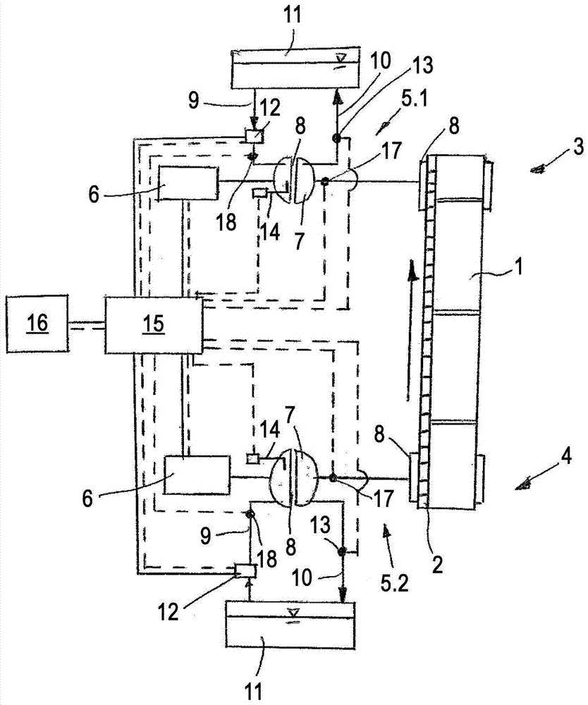
[0033] exist figure 1 shows a belt conveyor, for example as it is used in the mining industry. The conveyor belt 1 is driven by a chain 2 . The chain 2 is again driven in the region of the head 3 of the conveyor belt and the tail 4 of the conveyor belt by a respective dedicated drive train 5.1, 5.2.

[0034] A drive motor 6, here in the form of an electric motor, is arranged in each drive train 5.1, 5.2. Each drive motor 6 drives a drive pulley 8 for the chain 2 via a fluid coupling 7 . Each drive train 5.1, 5.2 can also be provided with several electric motors and / or hydraulic couplings.

[0035] Each hydrodynamic coupling 7 is filled with working medium via the inlet 9 and emptied of the working medium via the outlet 10 . Instead of the working chamber 8 shown here, the coupling hydrodynamics can also be designed with two parallel working chambers. A working medium, for example water, is supplied from a working medium storage container 11 , which is shown here as a conta...


PUM


Abstract

The method involves operating hydrodynamic clutch (7) in rated operation to preset time constant degree of filling of the working chamber (8), and time is changed at preset intervals for cooling of working medium in the working chamber by inlet (9) provided in the inlet valve (12) opened at intervals. The length of time between opening of intake valve, at which the inlet valve is kept closed as a function of calculated or recorded working fluid temperature in the working space in the outlet (10) and / or in inlet, is dynamically adjusted during operation of hydrodynamic clutch.

Description

technical field [0001] The invention relates to a method for controlling a hydraulic coupling, in particular in belt conveyors or chain conveyors, such as it is used in conveyors for the mining industry, for example in the drive motor and drive wheel or drive Face chain conveyor in drive train between shafts. Background technique [0002] Suitable hydraulic couplings are used in conveyor systems in the mining industry in order to be able to transport conveyor belts or conveyor chains without wear. Typically, multiple motors, in particular electric motors, are used for each belt or chain in order to drive the belt or chain. For example, a first motor or a plurality of first motors are arranged in the head region and a second motor or a plurality of second motors are arranged in the tail region, and these motors respectively drive the movement of the belt via one or more hydraulic couplings Or the drive wheel or drive shaft for that chain. [0003] As a rule, hydrodynamic c...

Claims


Application Information

Patent Timeline
Patent Type & Authority Patents(China)
IPC IPC(8): F16H61/48
CPCF16D33/16F16D48/06F16D2500/3022F16D2500/30404F16D2500/30426F16D2500/3166F16D2500/70448
Inventor 托尔斯藤·吕尔斯海莫·布雷格勒米夏埃尔·海尔卡马库斯·施洛瑟
Owner VOITH PATENT GMBH
Why Eureka
Try Eureka