A device for removing liquid accumulation on the piston of a dry gas cabinet

A technology of removal device and gas tank, which is used in gas/liquid distribution and storage, adjustable-capacity gas storage tanks, mechanical equipment, etc., can solve the problem that the inclination of the piston is difficult to guarantee, the normal production of the gas system has a great impact, and it is safe and reliable. It can eliminate problems such as unguaranteed performance, and achieve the effect of eliminating the phenomenon of shutdown and maintenance, the structure is simple and easy to implement, and the piston inclination exceeding the standard is eliminated.

Active Publication Date: 2017-07-11
CISDI ENG CO LTD
View PDF7 Cites 0 Cited by
  • Summary
  • Abstract
  • Description
  • Claims
  • Application Information

AI Technical Summary

Problems solved by technology

[0003] However, in typhoon-prone areas, when the typhoon passes through the dry gas tank, a large amount of rainwater will be brought in from the gas tank vent, causing a large amount of water to accumulate on the gas tank piston; Aging over time will cause rainwater to seep and drip onto the piston plate in rainy days to form an accumulation of liquid; in addition, when the sealing oil required for the piston sealing device of the thin oil-sealed dry-type gas cabinet flows down from the inner wall of the upper side plate of the gas cabinet, due to the oil distribution Unevenness, uneven inner wall and other reasons cause part of the sealing oil that should have entered the piston oil groove to splash on the piston plate to form fluid accumulation. The inclination of operation is difficult to guarantee, and the safety and reliability of its long-term operation cannot be guaranteed
[0004] In addition, there are usually the following inconveniences in using the traditional method to remove the liquid on the piston. First, because the lower cylinder of the dry-type gas holder is sealed, the connection cable for pumping liquid can only be lowered from the top of the gas holder. On the piston, the required cable is long, which is not conducive to saving costs; second, if the pump is temporarily used to drain the liquid by opening the manhole in the lower part of the dry gas tank, the piston needs to be lowered to the bottom of the gas tank, resulting in the sealing of the manhole It is troublesome and time-consuming, and has a great impact on the normal production of the gas system. Third, the existing method of manually removing the effusion is time-consuming and labor-intensive, and it is very dangerous for personnel to operate in the air space above the piston for a long time. Major and other issues

Method used


Image

  • A device for removing liquid accumulation on the piston of a dry gas cabinet
  • A device for removing liquid accumulation on the piston of a dry gas cabinet
  • A device for removing liquid accumulation on the piston of a dry gas cabinet

Examples


Embodiment Construction

[0028] The preferred embodiments of the present invention will be described in detail below in conjunction with the accompanying drawings; it should be understood that the preferred embodiments are only for illustrating the present invention, rather than limiting the protection scope of the present invention.

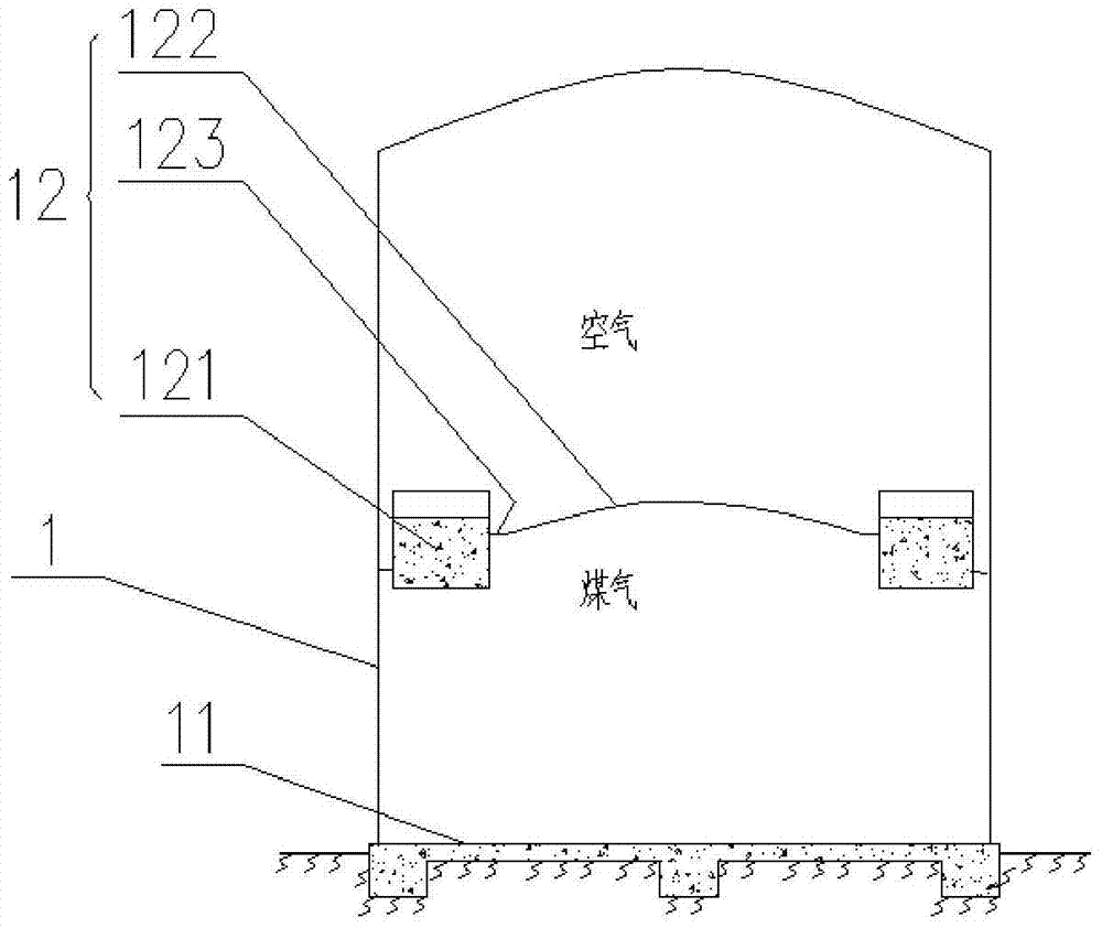
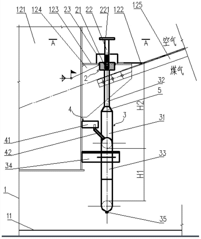
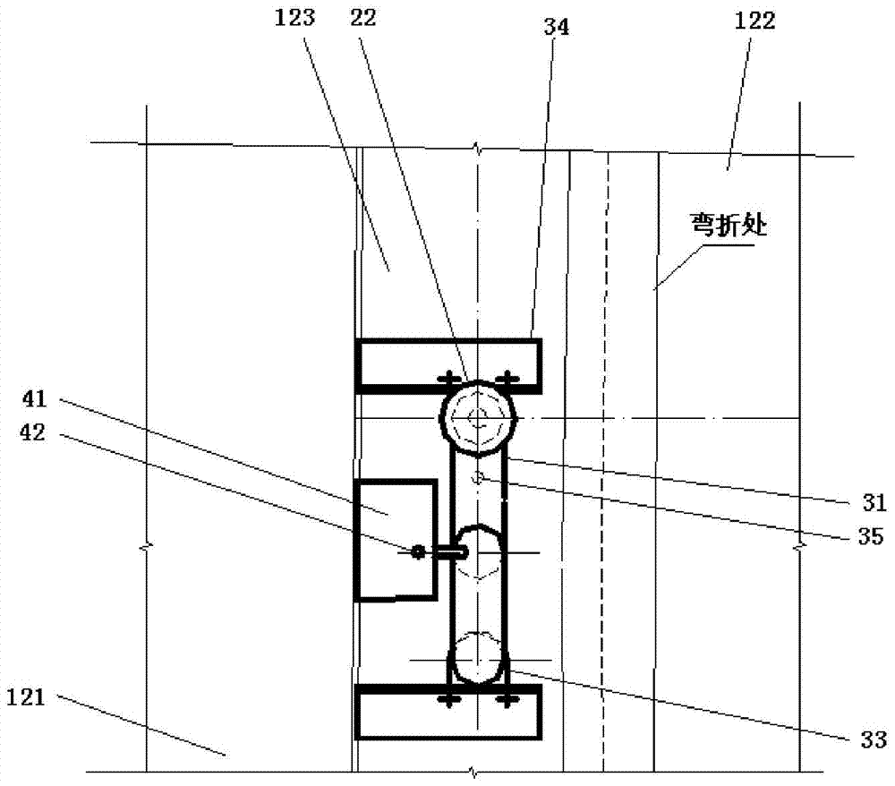
[0029] Such as Figure 1-3 As shown, the present invention provides a device for removing liquid accumulation on the piston of a dry gas cabinet. The dry gas cabinet 1 includes a bottom plate 11 and a piston 12, wherein the piston 12 is mainly composed of a piston box beam 121 and a piston arch. The piston The arch includes a piston arch high plate 122, a piston arch low plate 123 connected with the piston arch high plate 122, a support 124 for fixedly supporting the piston arch low plate 123, and an arch beam 125 for fixing and supporting the piston arch high plate 122. 124 is affixed on the piston box beam 121, and the arch beam 125 is affixed to the support 124; alon...


PUM


Abstract

The invention discloses a drainage draining device for a dry type gas holder piston. A plurality of drainage draining device bodies are evenly arranged in the radial direction of the piston and are mainly composed of liquid seal devices and plunger devices. The liquid seal devices comprise liquid storage bent pipes, liquid inlet pipes, liquid outlet pipes and supports, wherein the liquid storage bent pipes are located below piston arches, the liquid inlet pipes are communicated with one ends of the liquid storage bent pipes, the liquid outlet pipes are communicated with the other ends of the liquid storage bent pipes, and the supports are used for fixedly supporting the liquid storage bent pipes and are fixedly arranged on piston box beams. The plunger devices comprise plunger bodies fixedly connected with the piston arches and blocking rods detachably connected with the plunger bodies. The plunger bodies are internally and vertically provided with channels with inner threads. The lower ends of the channels are communicated with the liquid inlet pipes, the upper ends of the channels are communicated with the upper spaces of the piston arches, and the blocking rods are provided with outer threads connected with the inner threads in a matched manner. According to the drainage draining device, under the condition that the sealing performance of a gas holder is not affected, the drainage on the piston can be reliably drained through the water seal principle, the beneficial effect of high operability is achieved, and the running quality balance of the piston is ensured.

Description

technical field [0001] The invention belongs to the technical field of dry-type gas cabinets, and in particular relates to a device for removing liquid accumulation on the piston of a dry-type gas cabinet. Background technique [0002] Dry gas cabinet is an energy-saving and environment-friendly equipment in the field of gas recovery and utilization. Because its piston sealing device does not use water, it is called a dry gas cabinet compared with a wet gas cabinet. It has a piston sealing device that is safe and reliable. And other advantages, widely used in metallurgy, petrochemical, city gas and other industries. [0003] However, in typhoon-prone areas, when the typhoon passes through the dry gas tank, a large amount of rainwater will be brought in from the gas tank vent, causing a large amount of water to accumulate on the gas tank piston; Aging over time will cause rainwater to seep and drip onto the piston plate in rainy days to form an accumulation of liquid; in add...

Claims


Application Information

Patent Timeline
Patent Type & Authority Patents(China)
IPC IPC(8): F17B1/02F17B1/24
CPCF17B1/02F17B1/24
Inventor 高海平柳智钱力周伟刘俊鹏袁靖陈乐彭放林
Owner CISDI ENG CO LTD
Why Eureka
Try Eureka