target drone

A target machine and target shell technology, which is applied to targets, moving targets, offensive equipment, etc., can solve the problems of unable to meet the training needs of troops and shooting enthusiasts, unable to meet the training needs, and the training effect is not good, so as to meet the training requirements. , The effect of large randomness and wide target range

Active Publication Date: 2018-12-11
SHANGHAI BAORUI INFORMATION TECH DEV
View PDF6 Cites 0 Cited by
  • Summary
  • Abstract
  • Description
  • Claims
  • Application Information

AI Technical Summary

Problems solved by technology

[0002] The target machine, as a training device used for shooting training targets, has been widely used in various military exercises or weapon shooting tests, but since most of the existing shooting targets are generally fixed structures, that is, in a fixed The target rod is connected to the shooting target. This kind of fixed target can no longer meet the training needs of the troops and shooting enthusiasts. Therefore, in order to increase the difficulty of shooting, it has developed towards the direction of the mobile target machine.
[0003] However, the existing mobile target machines are generally divided into up-and-down targets and rotating targets. The up-down target means that the target rod is located at a fixed position on the target shell, and the rotating target means that the length of the target rod outside the target shell remains unchanged. shell rotation
Because the target position of the target machine is single, the trainees can easily memorize the target position and fix it directly at some fixed target position. The training effect is not good, and it cannot meet the training needs of actual combat.

Method used


Image

  • target drone
  • target drone
  • target drone

Examples


Embodiment Construction

[0031] In order to make the object, technical solution and advantages of the present invention clearer, various embodiments of the present invention will be described in detail below in conjunction with the accompanying drawings. However, those of ordinary skill in the art can understand that, in each implementation manner of the present invention, many technical details are provided for readers to better understand the present application. However, even without these technical details and various changes and modifications based on the following implementation modes, the technical solution claimed in this application can also be realized.

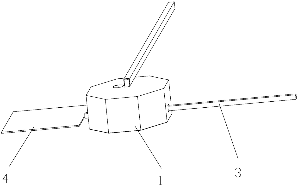
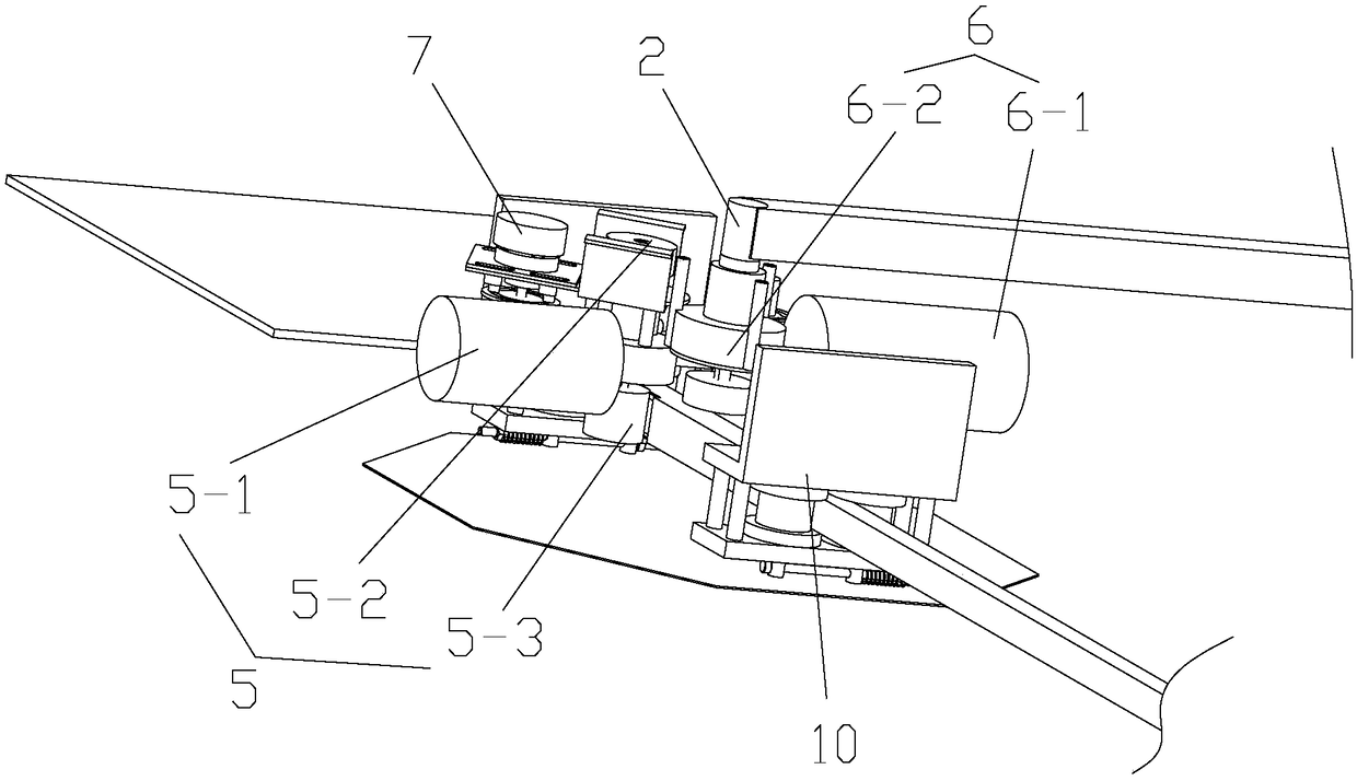
[0032] A first embodiment of the invention relates to a target rod. Such as figure 1 and figure 2 As shown, the target machine includes a target shell 1, a bearing seat 2 supporting the target shell 1, a target rod 3 passing through the target shell, and a target body 4 arranged at the end of the target rod 3, wherein the target shell 1 ...


PUM


Abstract

The invention relates to gunnery training devices, and discloses a target machine. The target machine comprises a target shell, a bearing pedestal for supporting the target shell and rotatably connected with the target shell, a target rod penetrating the target shell, a target body arranged at the end of the target rod, a first drive device connected with the target rod, a second drive device connected with the target shell and a master control system used for sending control instructions to the first drive device and the second drive device; the first drive device is used for driving the target rod to linearly move in the axis direction according to the control instructions sent by the master control system, and the second drive device is used for driving the target shell to rotate around the position of the connecting position of the bearing pedestal and the target shell as the pivotal point according to the instructions sent by the master control system. Compared with the prior art, the shooting difficulty of target practices can be improved, and the training needs are met.

Description

technical field [0001] The invention relates to a shooting training device, in particular to a target machine. Background technique [0002] The target machine, as a training device used for shooting training targets, has been widely used in various military exercises or weapon shooting tests, but since most of the existing shooting targets are generally fixed structures, that is, in a fixed The target pole is connected with the target for shooting. This kind of fixed target can no longer meet the training needs of troops and shooting enthusiasts at present. Therefore, in order to improve the difficulty of shooting, it has been developed in the direction of the mobile target machine. [0003] However, the existing mobile target machines are generally divided into up-and-down targets and rotating targets. Up-and-down targets mean that the target rod is located at a fixed position on the target shell, and the rotating target means that the length of the target rod outside the ...

Claims


Application Information

Patent Timeline
Patent Type & Authority Patents(China)
IPC IPC(8): F41J9/02
CPCF41J9/02
Inventor 鞠文海
Owner SHANGHAI BAORUI INFORMATION TECH DEV
Why Eureka
Try Eureka