Stretching cushion locking device

A locking device and a stretching pad technology, applied in the field of forging equipment, can solve the problems of large size, increased construction cost, complex structure, etc., and achieve the effects of satisfying strength and life, convenient manufacturing and maintenance, and simplifying equipment mechanism.

CN107377730AActive Publication Date: 2017-11-24福建合盈机械有限公司
3 Cites 2 Cited by

Patent Information

Authority / Receiving Office
CN · China
Patent Type
Applications(China)
Current Assignee / Owner
Publication Date
2017-11-24

Smart Images

  • Figure 1
    Figure 1
Patent Text Reader

Abstract

The invention discloses a stretching cushion locking device which comprises a stretching cushion cylinder, a draw bar, a locking sleeve, mounting plates, driving components, supports, movable plates, locking columns and springs. The stretching cushion locking device has the advantages that the movable plates can be driven by the driving components to move towards the centers of stretching cushions, and accordingly the locking columns can be driven by the movable plates to move towards the centers of the stretching cushions; at least a part of each locking column can extend into locking teeth on the corresponding locking sleeve at the moment and can mesh with the locking teeth, accordingly, the stretching cushion locking device has functions of preventing the draw bar from downwardly moving owing to the mode, the stretching cushions can be locked, the locking columns can be driven to outwardly move when the driving components move away from the centers of the stretching cushions, and the draw bar can freely move up and down; the stretching cushions can be locked at optional locations in controllable stroke ranges by the aid of simple and reliable mechanical transmission and locking structures of the stretching cushion locking device, accordingly, equipment and mechanisms can be simplified to a great extent, and spaces can be saved.
Need to check novelty before this filing date? Find Prior Art

Description

technical field

[0001] The invention relates to the field of forging equipment, in particular to a locking device for a stretching pad, which can be used to lock the stretching pad on a press. Background technique

[0002] The stretching pad is the mechanical component of the press to realize the stretching process and stamping. At present, the press equipment provided by domestic and foreign equipment suppliers mostly uses a locking valve to lock the hydraulic oil in the oil tank, so as to achieve locking. In order to adapt to the complex stretching process, the locking device usually needs to be able to adjust the locking position flexibly. In order to realize such adjustment, the equipment structure becomes more complicated.

[0003] As a typical example, the Chinese invention patent application with application number 2014108099320 (publication number CN104454783A) discloses a pure gas stretching pad structure with single crown and single master cylinder for a press, and...

Examples

Embodiment approach

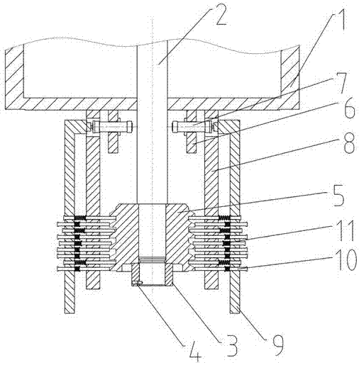
[0023] According to the first embodiment of the present invention, a locking device for stretching pads is proposed, which can be used to lock the stretching pads on the press, see the attached figure 1 , The structure of the device includes a tension pad cylinder 1, a pull rod 2, a nut 3, a pin 4, a locking sleeve 5, a mounting plate 6, a cylinder 7, a bracket 8, a moving plate 9, a locking column 10, and a spring 11.

[0024] The pull rod 2 is connected with the stretch pad piston (not shown in the figure), and moves up and down with the piston. The bottom of the stretch pad cylinder 1 is located on both sides of the pull rod 2 and is fixedly installed with a mounting plate 6 and a bracket 8. The mounting plate 6 is installed on On the inner side of the bracket 8, a cylinder 7 is fixedly installed on the mounting plate 6, and the piston rod of the cylinder 7 passes through the relief hole on the bracket 8 to connect to the moving plate 9 outside the bracket 8, so that the cyl...

Embodiment 2

[0027] The difference between this embodiment and Embodiment 1 is that the mechanical transmission device of screw feed is used to replace the cylinder 7, and other structures are the same as that of Embodiment 1. The mechanical transmission device of screw feed is the same as the cylinder, and belongs to The driving parts with reliable and stable power and simple structure have lower requirements on installation conditions and working environment than hydraulic systems.