Charge coil winding device

A winding device and charging coil technology, applied in the manufacture of circuits, electrical components, inductors/transformers/magnets, etc., can solve the problems of low efficiency, low yield rate, and close together, so as to solve the winding problem and improve the yield rate Effect

Active Publication Date: 2018-02-09
NANJING ANSEN ELECTRONICS CO LTD
View PDF6 Cites 0 Cited by
  • Summary
  • Abstract
  • Description
  • Claims
  • Application Information

AI Technical Summary

Problems solved by technology

[0002] As described in the patent CN201710452289, in order to improve the efficiency and performance of the coil, wireless charging uses a flat cable with a gap in the middle of the original cable to wind a flat coil; When winding, when encountering a corner, it is very easy to

Method used


Image

  • Charge coil winding device
  • Charge coil winding device
  • Charge coil winding device

Examples


Example Embodiment

[0026] The following describes the present invention in further detail with reference to the accompanying drawings and specific embodiments, without limiting the scope of implementation of the present invention.

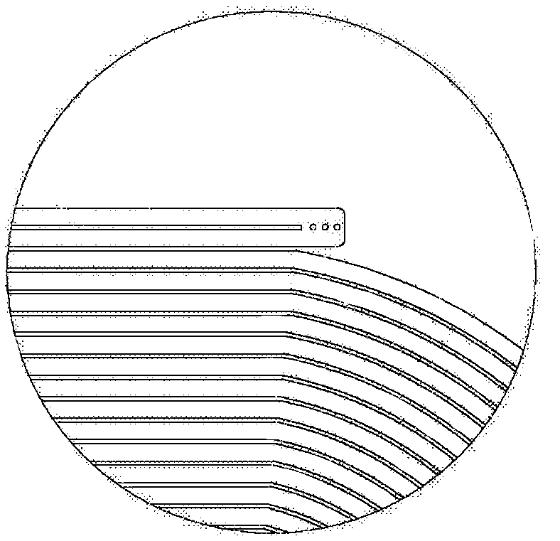
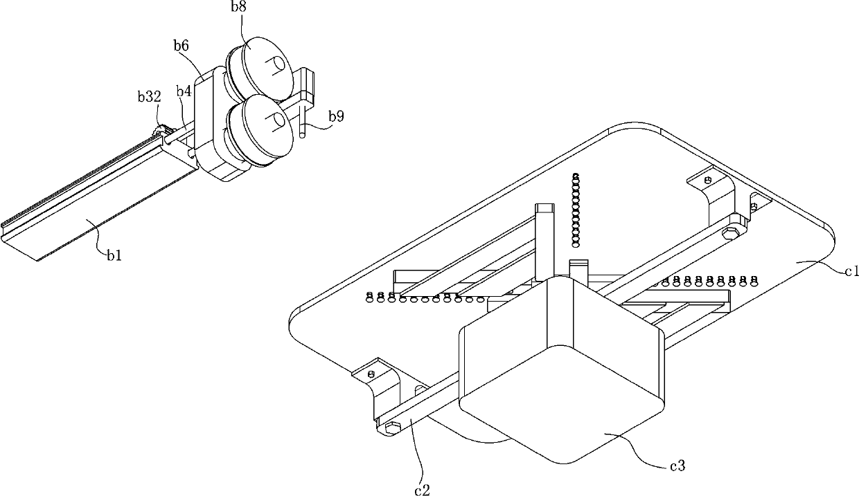
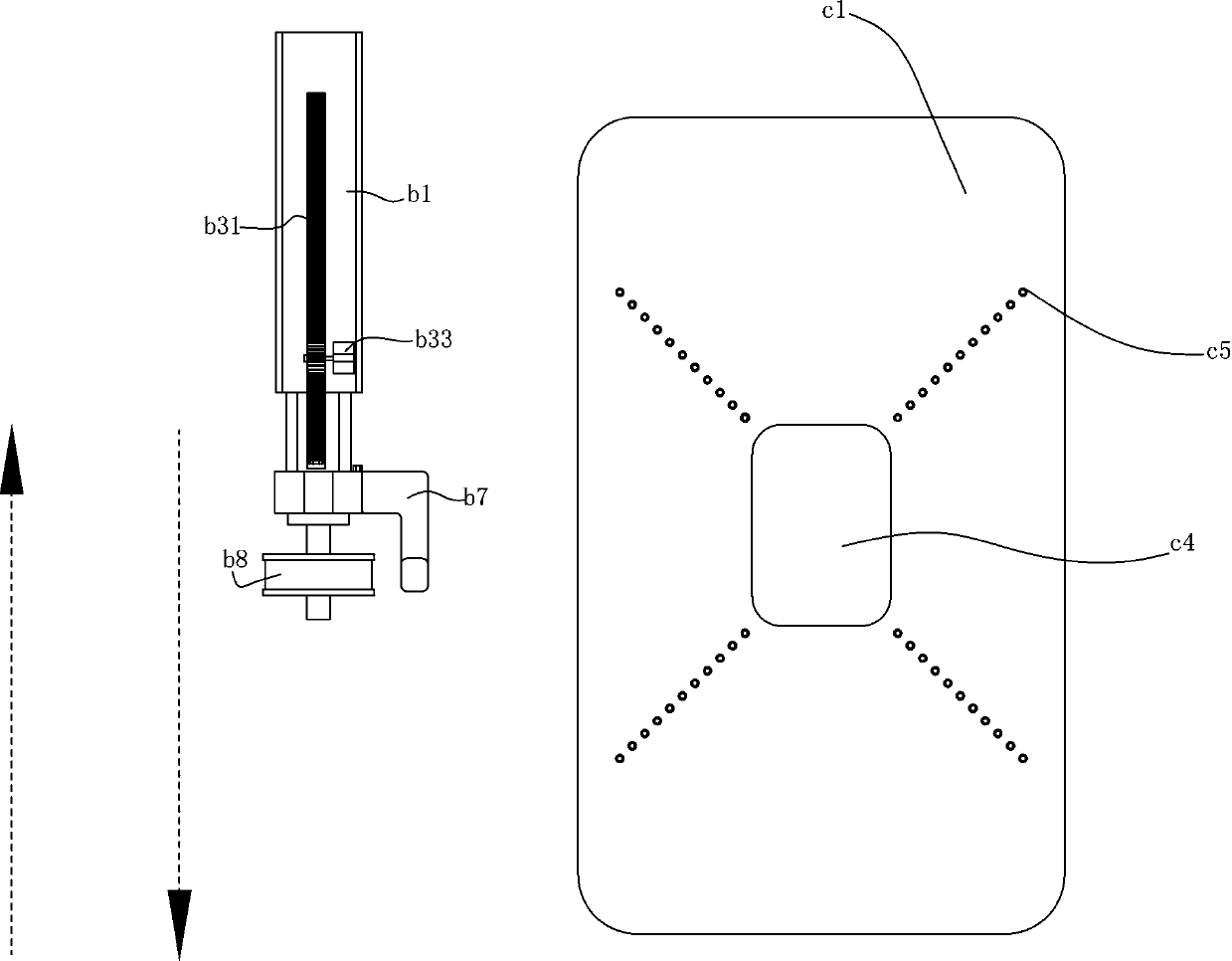
[0027] Such as Figure 1 to Figure 7 As shown, the charging coil winding device of this embodiment includes a cycloid mechanism and a rotating mechanism; the cycloid mechanism includes a fixed rod b1, a fixed block b6; a guide rod b4 is provided on the back of the fixed block b6, The fixed rod b1 is provided with a guide rod b2 corresponding to the guide rod b4, and the guide rod b4 of the fixed block b6 is slidably connected with the guide rod b2 of the fixed rod b1; it also includes a rack b31, one end of the rack b31 is fixed to the fixed The back of the block b6; also includes a first motor b33 arranged on the top surface of the fixed rod b1, the power output end of the first motor b33 is fixed with a gear b32 that cooperates with the rack b31; a second motor b51 is...


PUM


Abstract

The invention discloses a charge coil winding device. The charge coil winding device comprises a swinging mechanism and a rotating mechanism, wherein the swinging mechanism comprises a fixed bar and afixed block; a guide bar is arranged on the back of the fixed block, the fixed bar is internally provided with a guide tube corresponding to the guide bar, and the guide bar of the fixed block is insliding connection with the guide tube of the fixed bar. The charge coil winding device also comprises a rack, and one end of the rack is fixed on the back of the fixed block. The charge coil windingdevice also comprises a first motor arranged on the top surface of the fixed bar. The charge coil winding device solves the problem that the clearance becomes smaller during winding internally, and the winding problem is also solved while the yield is greatly improved.

Description

technical field [0001] The invention relates to a charging coil winding device. Background technique [0002] As described in the patent CN201710452289, in order to improve the efficiency and performance of the coil, wireless charging uses a flat cable with a gap in the middle of the original cable to wind a flat coil; When winding, when encountering a corner, it is very easy to make the gap between the flat wires smaller or even close together, causing the coil to be scrapped. At present, the winding is done manually. After winding, some tools are used to glue the wires together. It is inefficient to separate the gaps, and the yield rate is also very low. Contents of the invention [0003] The purpose of the present invention is to overcome the above-mentioned disadvantages and provide a charging coil winding device. [0004] In order to achieve the above object, the specific solution of the present invention is as follows: a charging coil winding device, including a cy...

Claims


Application Information

Patent Timeline
IPC IPC(8): H01F41/061
CPCH01F41/061
Inventor 王杰
Owner NANJING ANSEN ELECTRONICS CO LTD
Why Eureka
Try Eureka