
Photoelectric conversion module
A photoelectric conversion module and photoelectric coupling technology, applied in the directions of light guides, optics, optical components, etc., can solve the problems of difficult lens production, difficult measurement and confirmation of optical path alignment components, etc. The effect of easy alignment and mold size control
- Summary
- Abstract
- Description
- Claims
- Application Information
AI Technical Summary
Problems solved by technology
Method used
Image

Examples
Embodiment Construction
[0039] The present invention will be described in detail below in conjunction with the accompanying drawings.
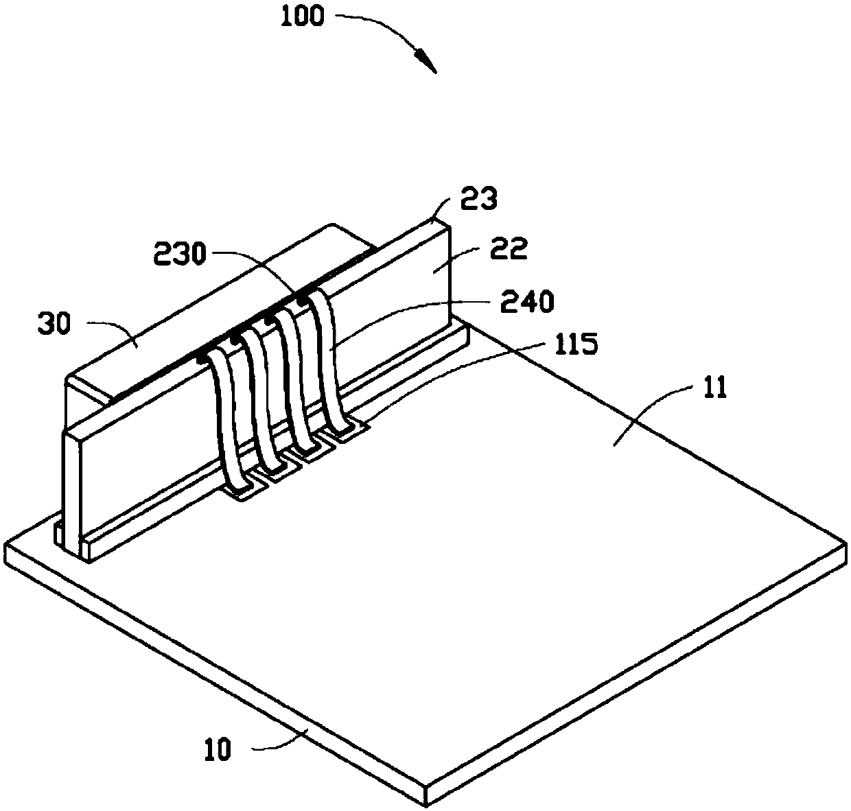
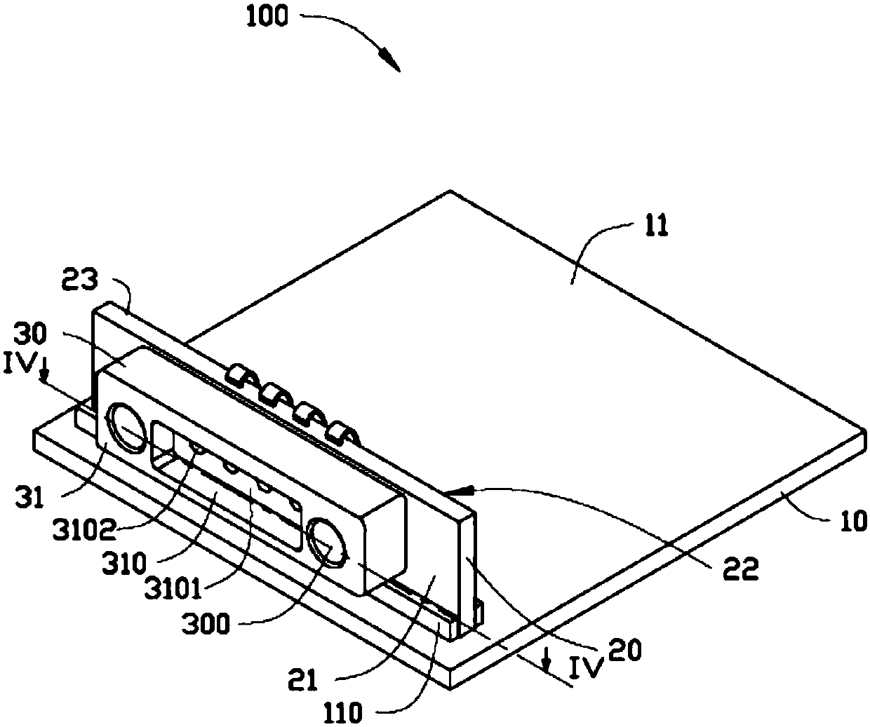
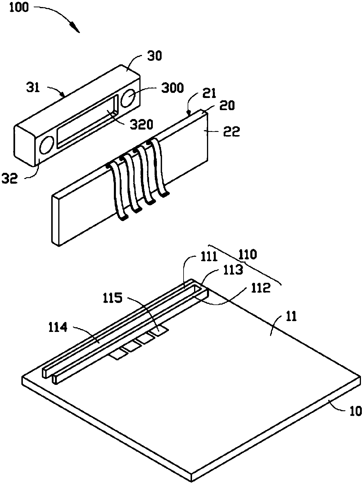
[0040] Please also refer to Figure 1 to Figure 4 , the photoelectric conversion module 100 provided by the embodiment of the present invention includes a main circuit board 10 , a sub-circuit board 20 , and a photoelectric coupler 30 .
[0041] The main circuit board 10 includes a bearing surface 11 . In this embodiment, a "U"-shaped positioning and fixing device 110 is provided on the bearing surface 11 . The fixing device 110 includes a first stop post 111, a second stop post 112 opposite to the first stop post 111, and a connecting link between the first stop post 111 and the second stop post 112. Connect the column 113 . The first blocking post 111 is parallel to the second blocking post 112 . The connecting column 113 is perpendicular to the first blocking column 111 and the second blocking column 112 . A receiving groove 114 is jointly formed between the ...
PUM
 Abstract
Description
Claims
Application Information