
paper shredder
A shredder, paper technology, applied in grain processing and other directions, can solve the problems of difficulty in stopping, pulling out, danger, etc., and achieve the effect of preventing shredding
- Summary
- Abstract
- Description
- Claims
- Application Information
AI Technical Summary
Problems solved by technology
Method used
Image

Examples
Embodiment Construction
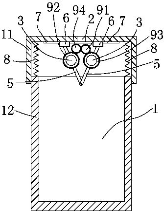
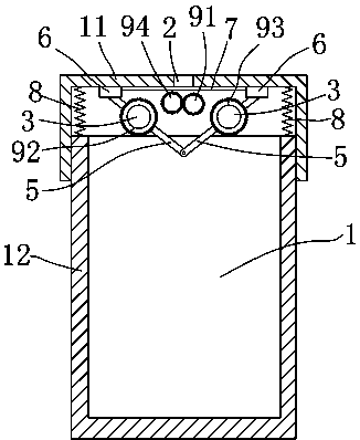
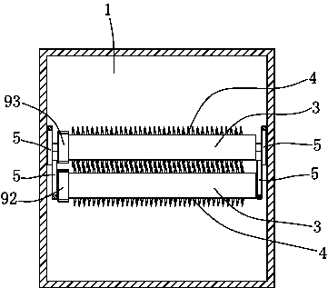
[0009] The present invention will be described in further detail below in conjunction with accompanying drawing and specific embodiment: see Figure 1 to Figure 3 , a paper shredder, comprising a box 1, the box 1 is provided with a strip-shaped opening 2 for putting in paper, the two sides of the strip-shaped opening 2 are provided with a rotating shaft 3, and the rotating shaft 3 is provided with a blade 4. The box 1 is also provided with a motor that drives the rotating shaft to rotate. The motor and the rotating shaft 3 are driven by gears. The box 1 includes an upper box 11 and a lower box 12. The upper box 1 The lower part of the box 11 is open, the upper part of the lower box 12 is open, the upper box 11 and the lower box 12 are moved in cooperation, and the lower box 12 is rotatably connected with two pairs of connecting rods 5. The lengths of the connecting rods 5 are all the same, the other end of the connecting rods 5 is connected with a slide block 6, the upper box ...
PUM
 Abstract
Description
Claims
Application Information