Method and apparatus for deriving a topograpy of an object surface

A technology of object surface and equipment, applied in the field of deriving the topography of object surface

Active Publication Date: 2018-04-17
QSO INTERFEROMETER SYST AB
View PDF7 Cites 2 Cited by
  • Summary
  • Abstract
  • Description
  • Claims
  • Application Information

AI Technical Summary

Problems solved by technology

Also, objects including polished surfaces can be very heavy

Method used


Image

  • Method and apparatus for deriving a topograpy of an object surface
  • Method and apparatus for deriving a topograpy of an object surface
  • Method and apparatus for deriving a topograpy of an object surface

Examples


Embodiment Construction

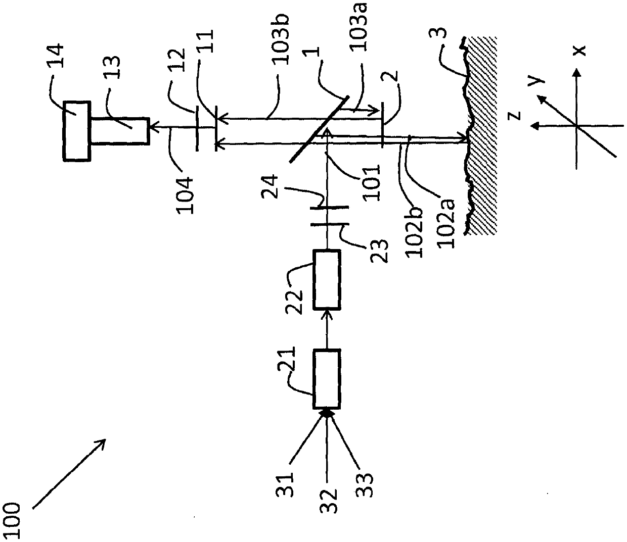
[0026] figure 1 An apparatus 100 is depicted according to some embodiments. The coordinate system used is figure 1 The bottom of is indicated by an arrow. The x-axis is the horizontal axis running from left to right along the paper, the y-axis is towards the inside of the paper, and the z-axis is the vertical axis running from bottom to top of the paper.

[0027] The object under inspection comprises an object surface 3 with a surface topography. The object surface 3 may also be referred to as surface. Topography refers to the three-dimensional arrangement of physical geometric 3-dimensional properties of a surface such as shape, height and depth, ie, the configuration of a surface including its protruding features and their locations.

[0028] The object surface 3 is irradiated with laser light via fibers 31, 32, 33 from separate monochromatic light sources, i.e. creating sinusoidal signals of different colors (in figure 1 not shown). The fibers 31 , 32 , 33 are connect...


PUM


Abstract

The embodiments herein relate to a method for deriving topography of an object surface (3). A linearly polarized light wave (102a, 103a) is directed towards the object surface (3) and a reference surface (2). Images of reflected linearly polarized light wave (102b, 103b) for a plurality of wavelengths are obtained. The images are obtained for at least four polarizations for each of the plurality of wavelengths. The reflected linearly polarized light wave (102b, 103b) is a reflection of the linearly polarized light wave (102a, 103a) directed towards the object surface (3) and the reference surface (2). The topography of the object surface (3) based on the obtained images is obtained.

Description

technical field [0001] Embodiments herein relate generally to a method and apparatus. More specifically, embodiments herein relate to deriving the topography of object surfaces. Background technique [0002] Surface modification, especially polishing, is a necessary process in many areas of industrial production. These include: [0003] · Automotive, for example, polishing of molds for plastic parts such as lids, lampshades and lenses. [0004] • Engine parts such as camshafts. [0005] • Surfaces of medical implants, for example, artificial hip joints. [0006] · Optical devices, such as injection molds for safety glass and contact lenses. [0007] Such polished surfaces on different types of objects can be several square meters in size and require a surface accuracy of 1 micron or less. Additionally, objects that include polished surfaces can be very heavy. Today, objects with polished surfaces are moved from the polishing process to the laboratory, where the surfac...

Claims


Application Information

Patent Timeline
Patent Type & Authority Applications(China)
IPC IPC(8): G01B11/24G01B9/02
CPCG01B9/02007G01B9/02057G01B11/2441G01B9/02087G01B9/02011G01B9/02005G01B2290/70G01B9/02078G06T7/564G06T7/521G06T7/60
Inventor L·博特
Owner QSO INTERFEROMETER SYST AB
Why Eureka
Try Eureka