Screw tightening assembly and tightening device

A component and screw technology, applied in the field of screw tightening components and tightening devices, can solve problems such as inconvenience, deformation, and no support.

Pending Publication Date: 2018-04-20
HERON INTELLIGENT EQUIP CO LTD
View PDF14 Cites 1 Cited by
  • Summary
  • Abstract
  • Description
  • Claims
  • Application Information

AI Technical Summary

Problems solved by technology

[0005] An object of the present invention is to provide a screw tightening assembly to solve the technical problems that the existing screw tightening assembly has no active self-aligning mechanism and the support will cause deformation, errors and inconvenient use

Method used


Image

  • Screw tightening assembly and tightening device
  • Screw tightening assembly and tightening device
  • Screw tightening assembly and tightening device

Examples


Embodiment 1

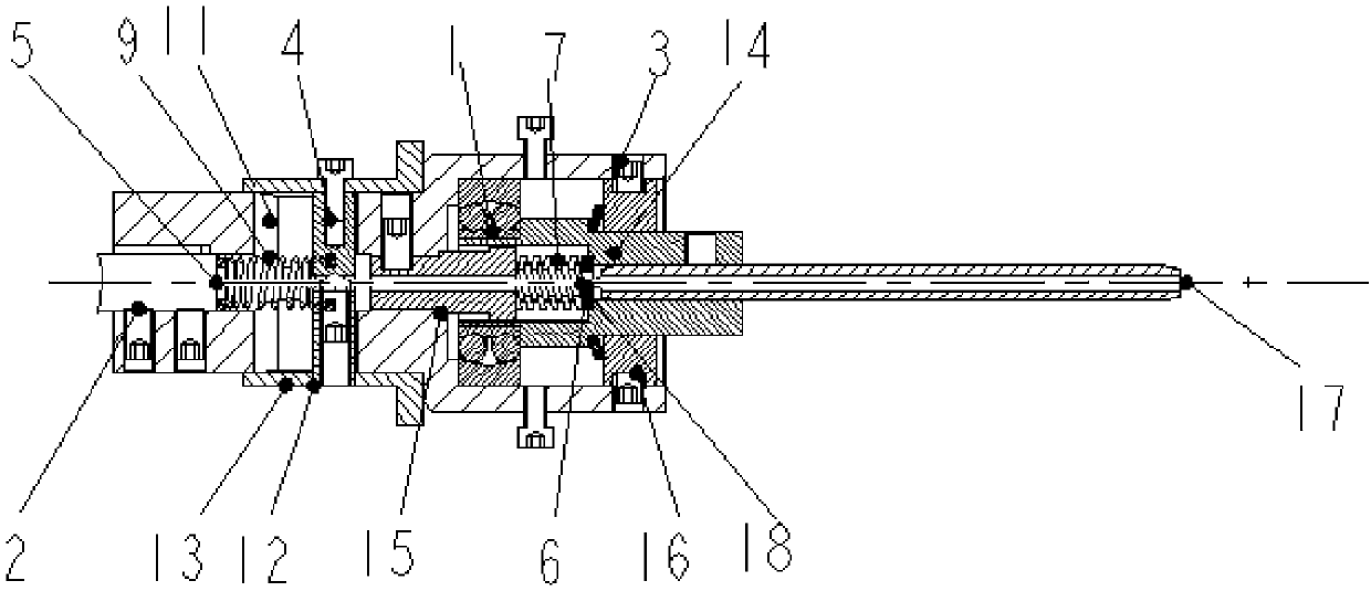
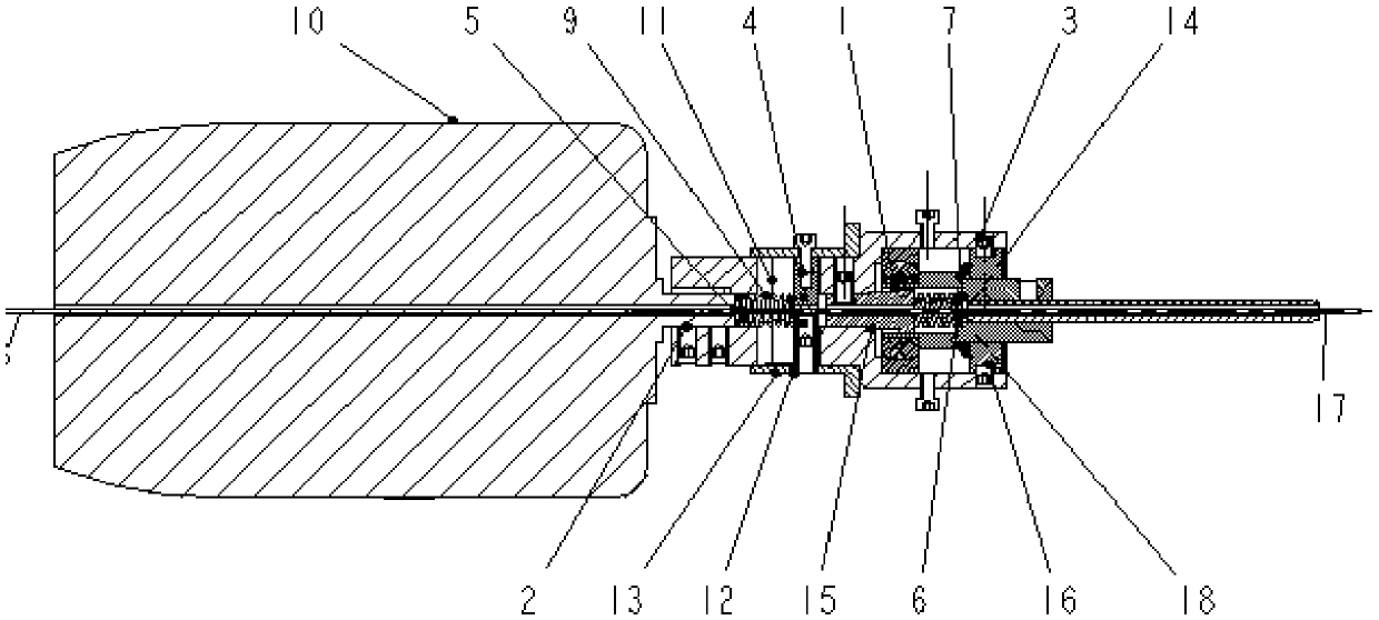
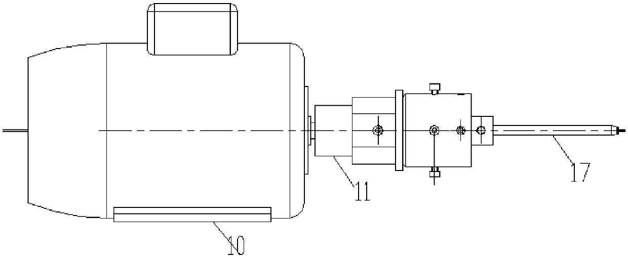
[0039] figure 1 A schematic diagram of the internal structure of the screw tightening assembly provided in Embodiment 1 of the present invention; figure 2 A schematic diagram of the internal structure of the screw tightening assembly and the motor provided in Embodiment 1 of the present invention; image 3 A schematic diagram of the external structure of the motor in the screw tightening assembly provided by Embodiment 1 of the present invention.

[0040] like Figure 1 to Figure 3 As shown, the screw tightening assembly provided by the embodiment of the first aspect of the present invention includes a transition shaft 11, a fixed shaft 14 and a screwdriver 17, a groove is arranged in the transition shaft 11, and the fixed shaft 14 is arranged in the concave In the groove, the screwdriver 17 is arranged in the fixed shaft 14 , and the self-aligning ball bearing 1 is arranged between the fixed shaft 14 and the transition shaft 11 .

[0041] In the screw tightening assembly ...

Embodiment 2

[0053] The shape of the cutter head 21 of the existing screwdriver 17 is a right-angle transition. When the locking process is carried out, the cutter head 21 will cause wear to the screw head, and the right angle will cause stress concentration, and the stress concentration will cause fatigue failure, reducing the use of the screwdriver 17. life.

[0054] like Figure 4 As shown, in any of the above technical solutions, further, the screwdriver 17 includes a knife shaft 20 and a knife head 21, and the knife shaft 20 and the knife head 21 transition through a slope.

[0055] The geometrical transition of the bit 21 of the screw is rounded, which improves the stress concentration, improves the service life of the screwdriver 17, and reduces the damage to the screw head during work.

[0056] In any of the above technical solutions, further, there are multiple cutter heads 21 , which are respectively arranged on the cutter bar 20 . And the screwdriver 17 is made into a double-e...


PUM


Abstract

The invention provides a screw tightening assembly and a tightening device and relates to the technical field of engineering machinery. The screw tightening assembly comprises a transition shaft, a fixing shaft and a screwdriver; a groove is formed in the transition shaft; the fixing shaft is disposed in the groove; the screwdriver is disposed in the fixing shaft; and a self-aligning ball bearingis disposed between the fixing shaft and the transition shaft. In the screw tightening assembly provided by the invention, the screwdriver is disposed in the fixing shaft, and the self-aligning ball bearing is disposed between the fixing shaft and the transition shaft. The self-aligning function is achieved through the self-aligning ball bearing so as to prevent errors, the colinearity of the rotation axis of the screwdriver can be guaranteed, and the advantages of good using effect and simple structure are achieved.

Description

technical field [0001] The invention relates to the technical field of engineering machinery, in particular to a screw tightening assembly and a tightening device. Background technique [0002] At present, the automatic screw tightening device used by foreign and some domestic companies is mainly used in the process of automatic locking of screws on bicycle vehicles. The screwdriver is driven by a motor, and the locking process is to lock the screw to the steel wire with threaded connection. . The driving device transmits the power to the handle of the screwdriver, transmits the torque to the screwdriver at the front end, and drives the screw to lock the screw in. [0003] What the support of screwdriver in the prior art used is common bearing support, and there is no active centering mechanism. First of all, due to the existence of manufacturing errors and assembly errors, it cannot be guaranteed that the screwdriver rotation axis is collinear with the rotation axis of th...

Claims


Application Information

Patent Timeline
Patent Type & Authority Applications(China)
IPC IPC(8): B25B21/00B25B15/00B25B23/00
CPCB25B15/001B25B21/00B25B23/00
Inventor 童灿钊
Owner HERON INTELLIGENT EQUIP CO LTD
Why Eureka
Try Eureka