Gluing device for medical needles

A gluing device and needle plate technology, which is applied to the surface coating liquid device, coating, etc., can solve the problems of uneven gluing, affecting the quality of injection needles, needle tube tilting, etc., and achieve the effect of uniform gluing

Active Publication Date: 2017-02-01
MAIDER MEDICAL IND EQUIP
View PDF1 Cites 0 Cited by
  • Summary
  • Abstract
  • Description
  • Claims
  • Application Information

AI Technical Summary

Problems solved by technology

[0004] Specifically, for example, a gluing device for a syringe needle loading machine disclosed in Chinese patent literature [Application No.: 201220354239.5], the patent discloses a gluing device, wherein the glue disc for gluing is located on the side of the needle tube, and the glue is applied During the process, the needle tube is clamped by the manipulator, so the glue plate can only apply glue to one side of the needle tube, so the glue is uneven; because the glue is thicker, most of the glue is still on the side of the needle tube before it solidifies. If there is too much glue on one side of the needle tube and too little water on the other side wall of the needle tube, the needle tube will tilt and affect Needle quality

Method used


Image

  • Gluing device for medical needles
  • Gluing device for medical needles
  • Gluing device for medical needles

Examples


Embodiment 1

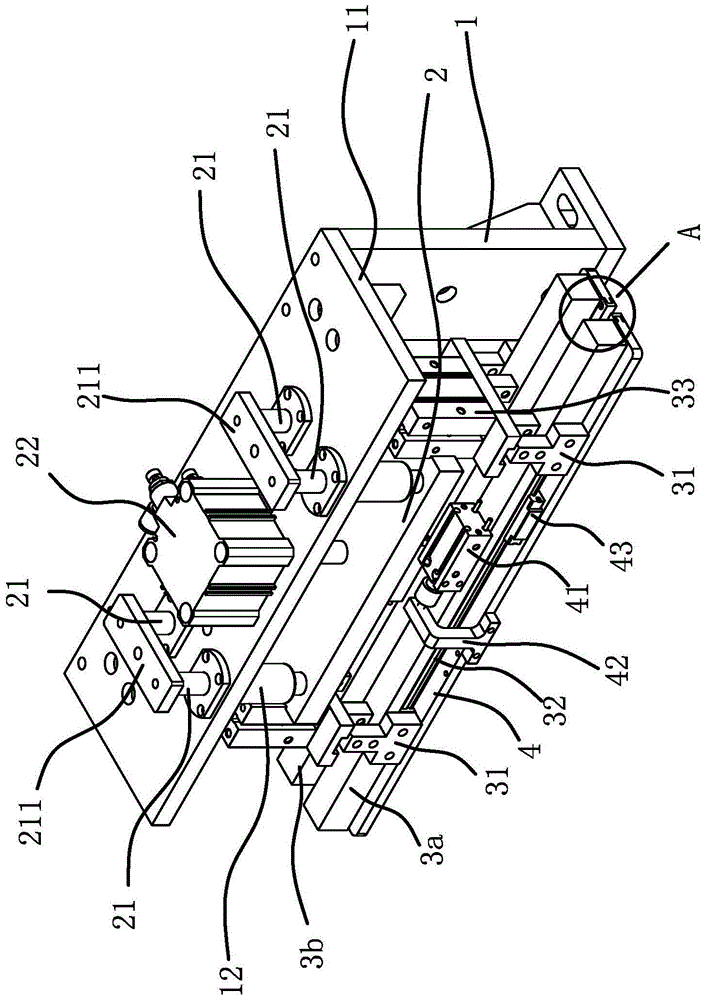
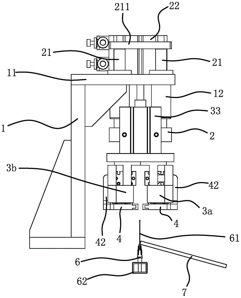
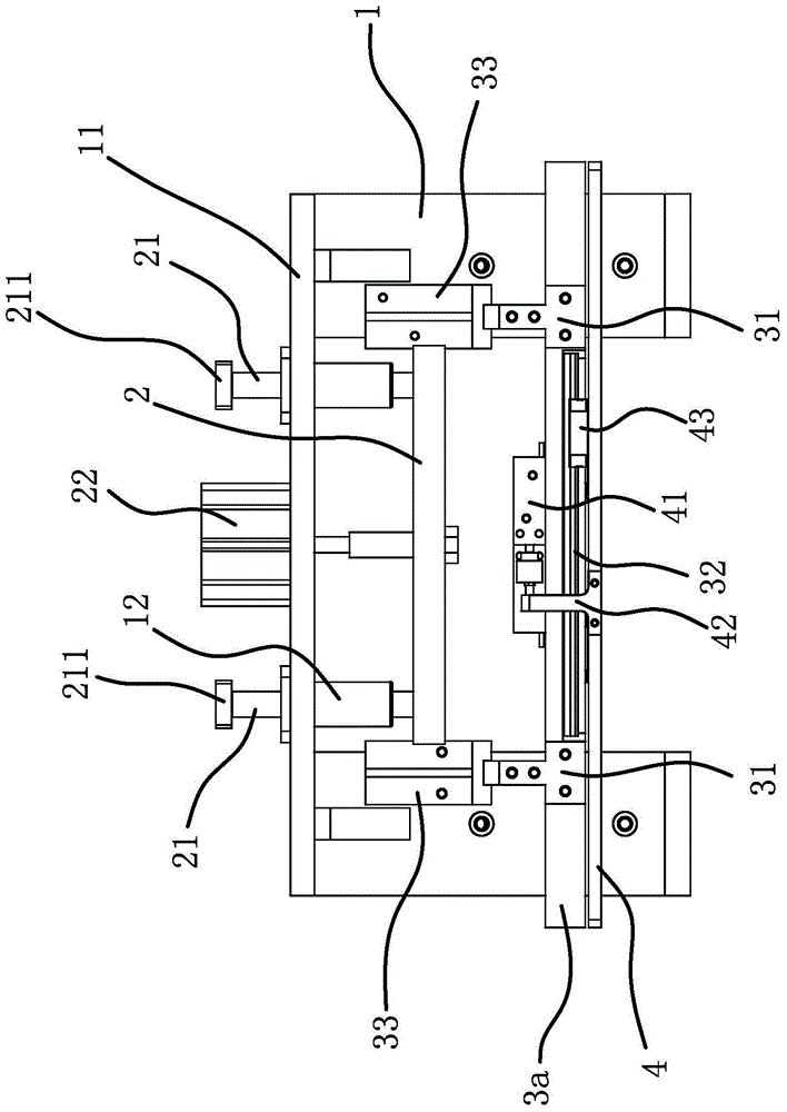
[0026] A glue coating device for medical needles, such as Figure 1 to Figure 5 As shown, it includes a frame 1, a lifting plate 2 and a rubber disc 7 for gluing. The frame 1 has a mounting table 11, and the mounting table 11 is provided with a clamping seat 62 for clamping the medical needle holder 6, and the needle tube 61 faces the mounting table 11 and is located between the rubbing plates 4 . The medical needles assembled by this gluing device are as follows: Figure 6 shown.

[0027] Such as Figure 1 to Figure 3 As shown, lifting plate 2 is located at the below of mounting platform 11, and driving source-22 is fixed on mounting platform 11, and driving source-22 can be cylinder, also can be motor, and driving source-22 cylinder in the present embodiment, the cylinder The cylinder body is fixed on the installation platform 11, and the telescopic rod of the cylinder is connected and fixed with the middle part of the lifting plate 2. The cylinder can drive the lifting p...

Embodiment 2

[0034] The structure and principle of this embodiment are basically the same as that of the first embodiment, except that the second driving source is a motor, the first mounting plate and the second mounting plate are vertically fixed with vertical plates, and screw rods are arranged between the vertical plates. The screw rod has opposite threads at two ends, and the two vertical plates are threadedly connected with the two ends of the screw rod respectively, the motor is fixed on the lifting plate, and the rotating shaft of the motor is fixed with the screw rod through a shaft coupling.


PUM


Abstract

The invention provides a glue coating device for medical needles, which belongs to the technical field of medical equipment manufacturing equipment. It solves the technical problems such as uneven glue application of the existing medical needle glue application device. The gluing device for medical needles includes a frame, a lifting plate connected with the frame and a rubber plate for gluing, the lifting plate is connected with a relatively set mounting plate 1 and mounting plate 2, mounting plate 1 and mounting plate 2. Through the relative or opposite movement of the driving source 2, the first mounting plate and the second mounting plate are respectively equipped with a needle rubbing plate, and the needle rubbing plate is respectively positioned by the driving source 3 fixed on the mounting plate 1 and the mounting plate 2. The opposite sides of the two rubbing plates on plate 1 and mounting plate 2 are clamping surfaces, and the clamping surfaces of the two rubbing plates can abut against each other and clamp the needle tube when mounting plate 1 and mounting plate 2 move relatively. The driving source three can drive the corresponding rubbing board to move along its length direction and the two rubbing boards move relatively. The invention has the advantage of being able to apply glue stably and evenly.

Description

technical field [0001] The invention belongs to the technical field of manufacturing equipment of medical instruments, and relates to a glue coating device for medical needles. Background technique [0002] Medical needles include infusion needles, injection needles, etc. The injection needle is a part of the syringe, including a needle seat and a needle tube. The needle seat has a needle tube installation hole, and the needle tube is inserted into the needle tube installation hole and fixed by glue. [0003] Injection needles are medical devices, and they should avoid contact with pollutants during the assembly process of injection needles. Therefore, they are currently assembled automatically by assembly machines. At present, the assembly of injection needles generally involves placing the needle base on the fixture, then inserting the needle tube into the needle tube installation hole of the needle base, and then applying glue to fix the two in the process. [0004] Spec...

Claims


Application Information

Patent Timeline
Patent Type & Authority Patents(China)
IPC IPC(8): B05C5/00B05C11/08B05C13/02
Inventor 林军华
Owner MAIDER MEDICAL IND EQUIP
Why Eureka
Try Eureka