
Mounting bracket for hydrological-engineering-environmental geological environment monitoring equipment

A technology for environmental monitoring and equipment installation, applied in the direction of measuring devices, mechanical equipment, machines/supports, etc., can solve problems such as tilting of monitoring equipment, affecting measurement results, troublesome adjustment, etc., to achieve the effect of avoiding tilting and simple adjustment process

Pending Publication Date: 2021-12-17
山东省地质矿产勘查开发局第四地质大队
View PDF8 Cites 2 Cited by
  • Summary
  • Abstract
  • Description
  • Claims
  • Application Information

AI Technical Summary

Problems solved by technology

[0003] At present, most of the brackets used for hydraulic, environmental and geological environment monitoring are directly opened on the ground when in use. If the ground is uneven, the bracket will be inclined as a whole. At this time, the staff need to manually adjust the support structure of the bracket. During this process, the staff Only relying on the naked eye to observe whether the bracket is in a horizontal state is cumbersome in the adjustment process, and it is difficult to ensure that the bracket is in a horizontal state. When monitoring the equipment during use, the staff needs to turn the monitoring equipment, align the monitoring equipment with the monitoring direction, and then move the monitoring equipment Placed on the bracket, it is easy to cause the monitoring equipment to tilt when placed, which will affect the measurement results

Method used


Image

  • Mounting bracket for hydrological-engineering-environmental geological environment monitoring equipment
  • Mounting bracket for hydrological-engineering-environmental geological environment monitoring equipment
  • Mounting bracket for hydrological-engineering-environmental geological environment monitoring equipment

Examples


Embodiment Construction

[0025] In order to make the technical means, creative features, goals and effects achieved by the present invention easy to understand, the present invention will be further described below in conjunction with specific embodiments.

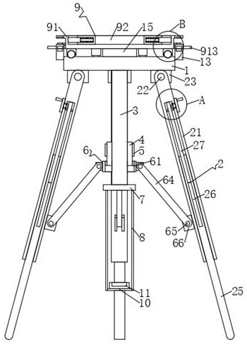
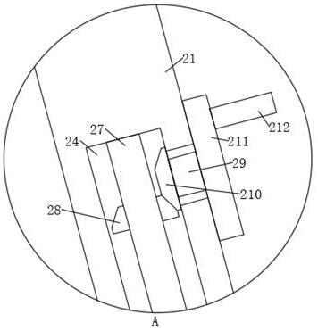
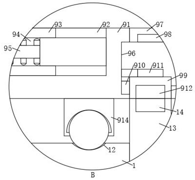
[0026] Such as Figure 1-Figure 7 As shown, a hydraulic ring geological environment monitoring equipment installation bracket according to the present invention includes a carrier plate 1, the carrier plate 1 has a circular structure, and three supports are installed at equal intervals on the lower edge of the carrier plate 1 Mechanism 2, the middle part of the lower end of the carrier plate 1 is fixedly connected with a second screw rod 3, the outer wall of the middle part of the second screw rod 3 is sheathed and threadedly connected with a screw sleeve 4, and the lower end of the screw sleeve 4 is installed with a support Lifting mechanism 6, the supporting mechanism 6 is connected with three supporting mechanisms 2, the lower end of the second...


PUM


Abstract

The invention relates to the field of hydrological-engineering-environmental geological environment monitoring, in particular to a mounting bracket for hydrological-engineering-environmental geological environment monitoring equipment, which comprises a carrier plate, wherein the carrier plate is of a circular structure, three supporting mechanisms are mounted at the edge of the lower end of the carrier plate at equal intervals, and a second screw is fixedly connected to the middle of the lower end of the carrier plate; and the circumferential outer wall of the middle part of the second screw is sleeved and in threaded connection with a screw sleeve. The upper end of the carrier plate is connected to a placing mechanism through a movable shaft, a sliding ring provided with a first magnet ring is mounted on a carrying disc of the placing mechanism, the first magnet ring corresponds to a second magnet ring mounted on the carrying plate; during use, monitoring equipment can be fixed in the placing groove in the carrying disc, then the carrying disc is rotated, so that the angle of the monitoring equipment is adjusted; Then the first magnet ring is attracted to the second magnet ring, the position of the carrying disc is fixed, then the alignment direction of the monitoring equipment is fixed, the monitoring equipment does not need to be moved in the process, and therefore, the situation that the monitoring equipment inclines is avoided.

Description

technical field [0001] The invention relates to the field of hydraulic environment geological environment monitoring, in particular to a hydraulic environment geological environment monitoring equipment mounting bracket. Background technique [0002] The geological environment mainly refers to the hard shell below the earth's surface, namely the lithosphere. The geological environment is a product of the evolution of the earth. The weathering process of rocks under the action of solar energy liberates the consolidated matter, participates in the geographical environment, participates in the geological cycle and the great cycle of interstellar matter, and is composed of rocks, floating soil, water and the atmosphere. , When the staff uses the monitoring equipment, they usually use a bracket to install the monitoring equipment on the ground. [0003] At present, most of the brackets used for hydraulic, environmental and geological environment monitoring are directly opened o...

Claims


Application Information

Patent Timeline
IPC IPC(8): F16M11/04F16M11/08F16M11/16F16M11/34G01N33/24G01D11/30G01D11/16
CPCF16M11/04F16M11/08F16M11/16F16M11/34G01N33/24G01D11/30G01D11/16
Inventor 黄鑫聂西坤张天然
Owner 山东省地质矿产勘查开发局第四地质大队
Learn More