Integrated lock and tilt-latch mechanism for a sliding window

a sliding window and lock technology, applied in the field of window locks, can solve the problems of poor washability of traditional double-hung window designs, inconvenient operation, and poor washing

Inactive Publication Date: 2011-06-21
TRUTH HARDWARE
View PDF86 Cites 48 Cited by
  • Summary
  • Abstract
  • Description
  • Claims
  • Application Information

AI Technical Summary

Benefits of technology

[0011]The present invention addresses the need for a low-cost combination tilt-lock-latch mechanism for a sliding window that combines ease of installation and adjustment, simplicity of use, and a bias toward a locked or unlocked position. In embodiments of the invention, an integrated lock and tilt-latch mechanism for a sliding window includes at least one tilt-latch mechanism adapted for mounting in the window sash. The tilt-latch mechanism includes a housing presenting a longitudinal axis and having an aperture defined in a first end thereof, a plunger having a latch-bolt portion, a plunger-latch member, and first and second biasing members. The plunger is disposed in the housing and is selectively slidably shiftable along the longitudinal axis of the housing between an extended position in which the latch-bolt portion of the plunger projects through the aperture in the housing to engage the window frame so as to prevent tilting of the sash, and a retracted position in which the latch-bolt portion of the plunger is substantially within the housing to enable tilting of the sash. The first biasing member is arranged so as to bias the plunger toward the extended position. The plunger-latch member is operably coupled with the tilt-latch housing and is arranged so as to be selectively slidably shiftable in a direction transverse to the longitudinal axis when the plunger is in the retracted position. The plunger-latch member is shiftable between a first position in which the plunger-latch member engages and prevents shifting of the plunger and a second position in which the plunger-latch member enables shifting of the plunger. The second biasing member is arranged so as to bias the plunger-latch member toward the first position so that when the plunger is retracted, the plunger-latch automatically shifts to retain the plunger in the retracted position. The plunger-latch may include a trigger portion arranged so that when the sash is tilted into position in the frame, the trigger portion contacts the window frame or second sash, shifting the plunger-latch so as to release the plunger. The mechanism further includes an actuator mechanism adapted for mounting on the sash. The actuator mechanism includes a housing, a control on the housing, a lock member, and a tilt-latch actuator member. The lock member and the tilt-latch actuator member are operably coupled with the control. A linking member operably couples the tilt-latch actuator member and the plunger of the tilt-latch mechanism. The control lever is selectively positionable between at least three positions, including a locked position in which the sweep cam is positioned so that a portion of the sweep cam extends under the locking tab of a keeper, an unlocked position in which the sweep cam is substantially retracted from the locking tab of a keeper, and a tilt position in which the sweep cam is retracted and the plunger of the tilt-latch mechanism is positioned in the retracted position.

Problems solved by technology

Traditional double-hung window designs provide poor washability, because it is difficult for a person located inside a structure in which the window is installed to wash the outside of the window pane.
This is not only extremely inconvenient, as the person has to walk significant distances merely to wash both sides of a single window, but it can also force a window washer, when trying to wash double and single-hung windows located at significant heights, to face the undesirable choice of either risking injury by climbing to that height or doing a relatively poor job of washing by merely reaching from a distance with a hose or a special long pole apparatus of some type.
Such cleaning is still further complicated where there are screens or storm windows that must be removed prior to washing.
A drawback of such mechanisms, however, is that both latches must be operated simultaneously, requiring that the operator use both hands.
Moreover, simultaneous operation of latch controls spaced at the far edges of the sash can be awkward, especially for wide windows.
This is inconvenient and may result in unintended tilting operation of the window if an inexperienced user seeking merely to unlock the window rotates the lever in the wrong direction.
The '700 patent mechanism, while enabling same-direction rotation of the control lever, is relatively complex, and may be expensive to manufacture and difficult to install and adjust.
The '142 patent mechanism may be difficult to adjust, requiring partial disassembly and manipulation of a screw on the tilt latches for tensioning the strap connecting the control lever with the tilt latches.
This may be confusing for a user and result in frustration when attempting to tilt the window for cleaning, or in failure to properly reengage the tilt latches when cleaning is complete.
A drawback of this mechanism, however, is that it is relatively complex, including a spring-loaded control lever and a pivoting trigger release mechanism in each of the tilt latches, making it relatively more expensive to produce and reducing reliability.
Further, there are no simple means provided for attaching the extensible member to the tilt latches, nor is any means for adjusting length and tension of the extensible member provided.
One drawback of this mechanism, however, is that a relatively complicated fastener arrangement is used for connecting the actuator spool to the tilt latch connector, affecting cost of manufacture and usability of the mechanism.
Also, the tilt latches are not equipped with any mechanism for holding the latches in the retracted position.
When the window is tilted into position after cleaning, the protruding latch-bolts may mar the window frame if the operator forgets to manually retract them.
Moreover, a separate button is described that must be manipulated for engaging or releasing the tilt latches, thus complicating operation.
One drawback of this mechanism, however, is that the lever may remain in the window-tilt position unless an operator manually returns the lever to the locked or unlocked positions.
Moreover, it may be difficult for an operator to judge when the lever has been correctly positioned to a tilt, locked, or unlocked position.

Method used


Image

  • Integrated lock and tilt-latch mechanism for a sliding window
  • Integrated lock and tilt-latch mechanism for a sliding window
  • Integrated lock and tilt-latch mechanism for a sliding window

Examples


Embodiment Construction

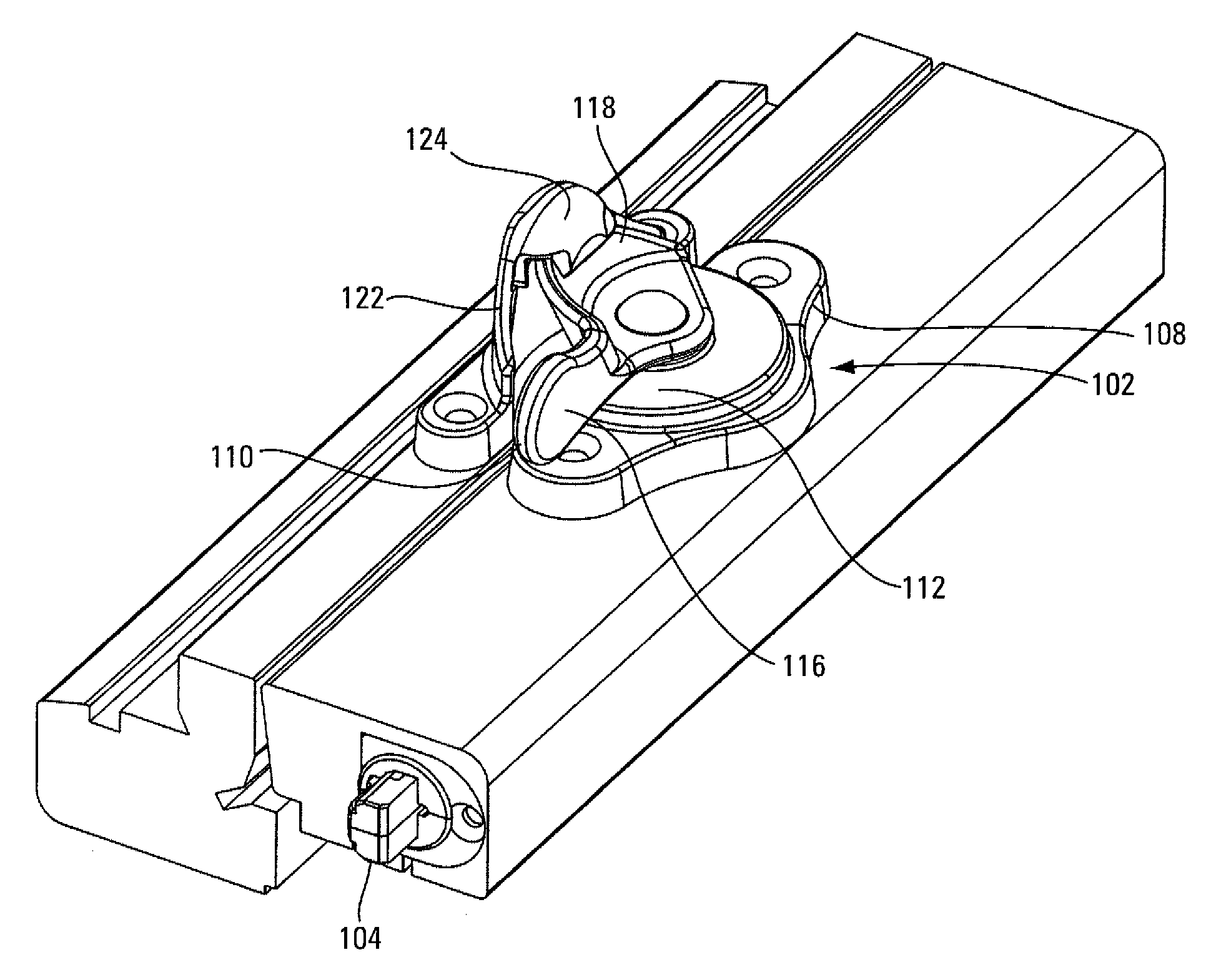
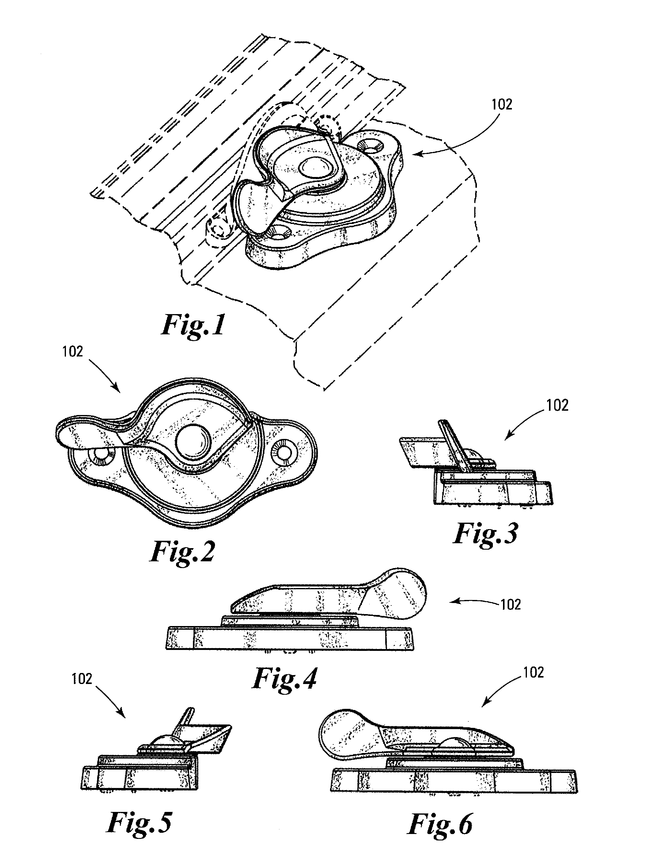
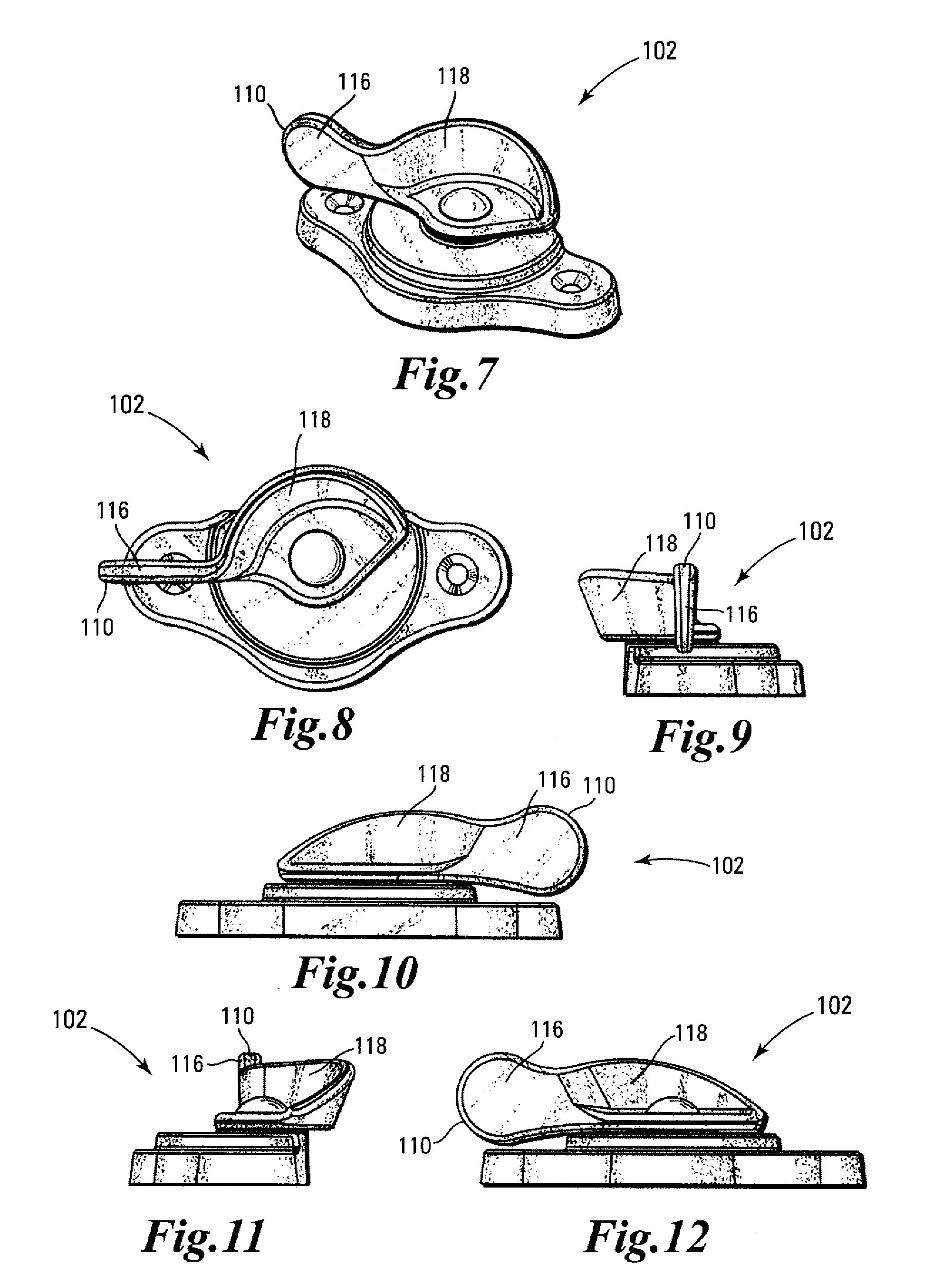
[0087]Locking tilt-latch assembly 100 is generally mounted onto double-hung window, as depicted in FIG. 13. As depicted in FIG. 14, locking tilt-latch assembly 100 generally includes actuator assembly 102, tilt-latch assemblies 104, and linking member 106. Actuator assembly 102 generally includes base assembly 108 and control lever 110. Base assembly 108 is defined by baseplate 112 and base housing 114. In an example embodiment, baseplate 112 and base housing 114 are assembled together such that baseplate 112 defines the top of base assembly 108, as depicted in FIG. 15. Control lever 110 has handle 116, sweep cam 118, and shank 120. Sweep cam 118 is generally tapered away from handle 116. As control lever 110 rotates, sweep cam 118 engages or disengages keeper 122. When control lever 110 is in a locked position, as depicted in FIG. 15, sweep cam 118 is positioned under and within locking tab 124 of keeper 122. Inside sash 310 of double-hung sash window 312 is thereby substantially p...


PUM


Abstract

An integrated lock and tilt-latch mechanism for a sliding window including an actuator assembly operably connected by a flexible linking member to at least one tilt-latch mechanism adapted for mounting in a window sash. The actuator assembly includes a control lever that rotates a sweep cam and a selectively rotates a spool, thereby locking or unlocking the sliding window or actuating the tilt-latch mechanism. At least one biasing member causes the control lever to favor locked or unlocked positions over intermediate and tilt positions.

Description

FIELD OF THE INVENTION[0001]This invention relates to window locks, and more particularly to window locks for sliding windows.BACKGROUND OF THE INVENTION[0002]Double-hung and single hung sliding windows include two window sashes typically mounted for vertical movement along adjacent parallel tracks in a window frame. Traditional double-hung window designs provide poor washability, because it is difficult for a person located inside a structure in which the window is installed to wash the outside of the window pane. To fully wash the outer surface of such windows (which outer surface is the one which is most often in need of cleaning), the person cleaning the window must typically go outside the dwelling. This is not only extremely inconvenient, as the person has to walk significant distances merely to wash both sides of a single window, but it can also force a window washer, when trying to wash double and single-hung windows located at significant heights, to face the undesirable ch...

Claims


Application Information

Patent Timeline
Patent Type & Authority Patents(United States)
IPC IPC(8): E05C3/04E05C3/00
CPCE05C3/046E05C9/04E05C9/00E05C9/002E05B53/003E05C2007/007Y10T292/0844Y10S292/20Y10S292/47Y10T292/1041Y10T292/0839
Inventor WOLF, GLEN
Owner TRUTH HARDWARE
Why Eureka
Try Eureka