Connector with resin molded portion

Inactive Publication Date: 2006-03-28
MITSUMI ELECTRIC CO LTD
View PDF5 Cites 51 Cited by
  • Summary
  • Abstract
  • Description
  • Claims
  • Application Information

AI Technical Summary

Benefits of technology

[0013]In view of the problems described above, it is an object of the present invention to provide a connector which can prevent misalignment of an inner molded portion without the use of bosses when an outer molded portion is formed.
[0015]According to the present invention, it is possible to prevent misalignment of the inner molded portion with respect to the outer molded portion when the outer molded portion is formed by providing the positioning means on the inner molded portion. Further, it is also possible to prevent the outer molded portion from having an uneven wall thickness due to the misalignment of the inner molded portion. Further, since the positioning means are provided on the inner molded portion, it is unnecessary to provide bosses on the metal molds for press molding the outer molded portion. As a result, it is possible to prevent a problem caused by boss holes that remain in the outer molded portion.
[0017]As described above, since the pair of protrusions protrude toward a pair of molds for molding the outer molded portion, respectively, the distance from the surface of both metal molds to the inner molded portion can be regulated accurately. In this way, the positioning of the inner molded portion in this direction can be carried out with high accuracy.
[0019]As described above, since the pair of protrusions respectively protrude from the corresponding parts of the left and right surfaces of the inner molded portion in a symmetrical manner, the pressure of both metal molds is applied evenly to each protrusion. For this reason, it is possible to efficiently prevent misalignment of the inner molded portion with respect to the outer molded portion due to the pressure of the both metal molds.
[0021]Since the pair of positioning portions extend along an inclination restricting direction on the inner molded portion as described above, it is possible to prevent inclination of the inner molded portion in the extending direction of the positioning portions over large area.

Problems solved by technology

Further, since the positioning means are provided on the inner molded portion, it is unnecessary to provide bosses on the metal molds for press molding the outer molded portion.

Method used


Image

  • Connector with resin molded portion
  • Connector with resin molded portion
  • Connector with resin molded portion

Examples


Embodiment Construction

[0031]The preferred embodiment of a connector according to the present invention is described below with reference to the drawings.

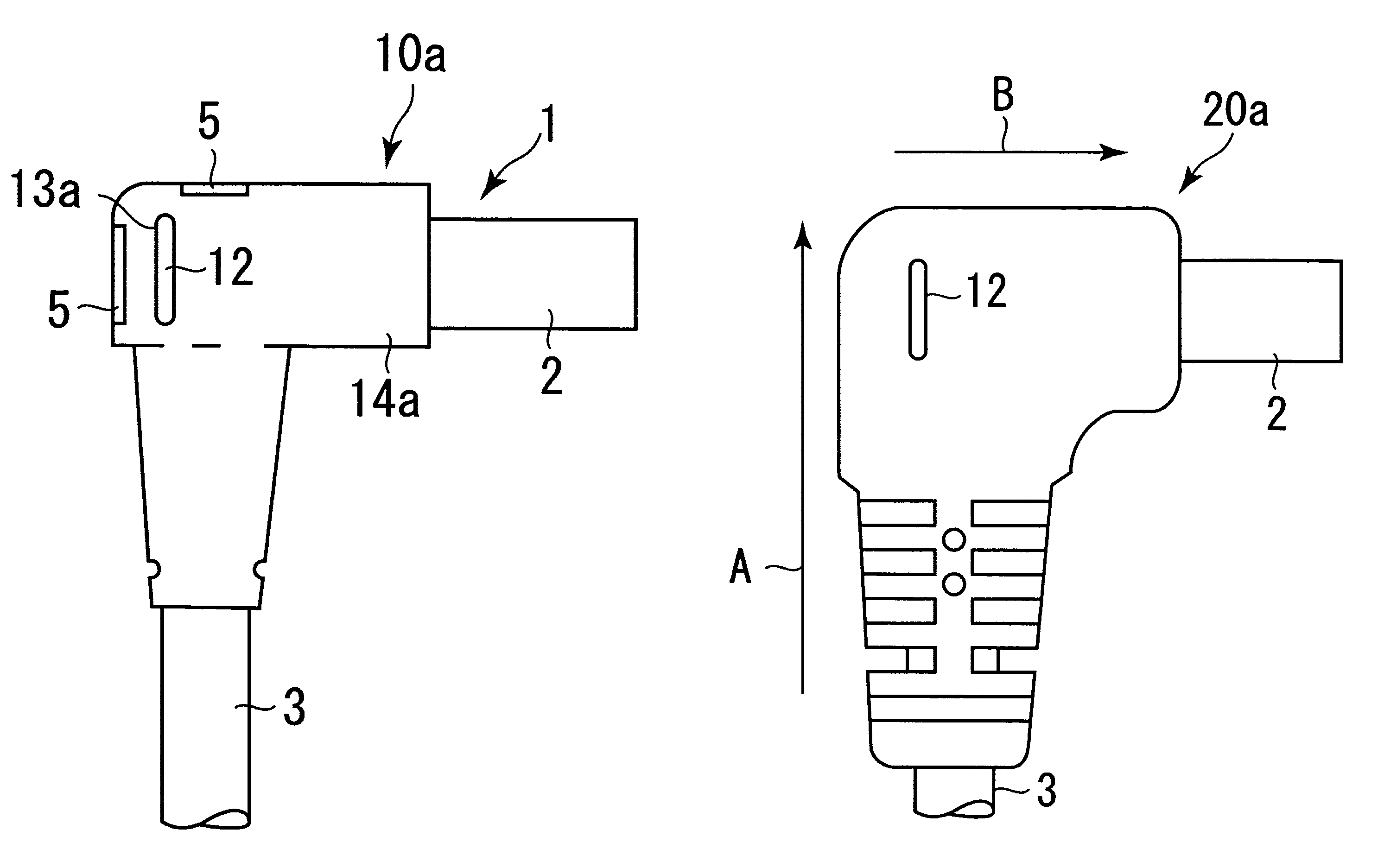
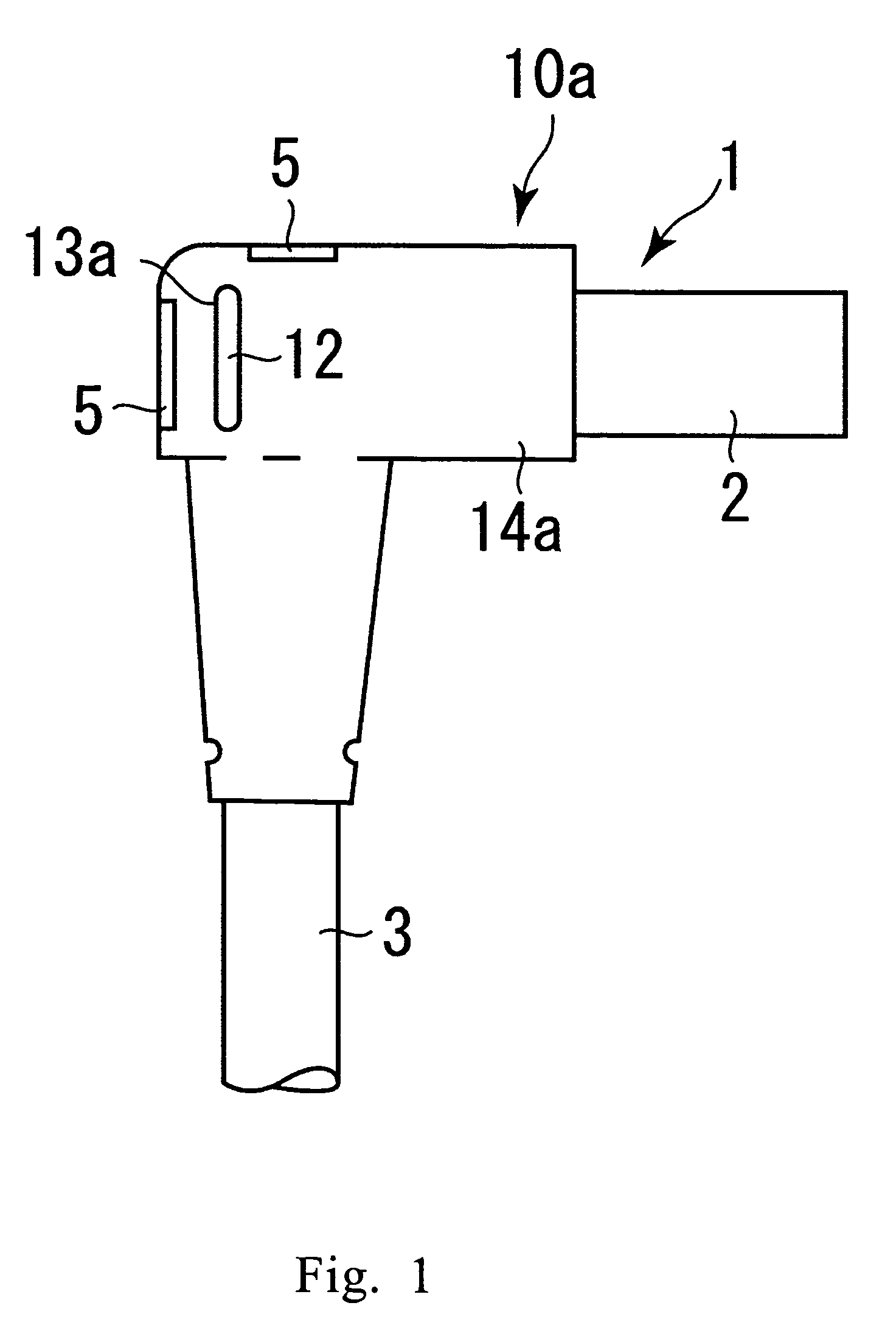
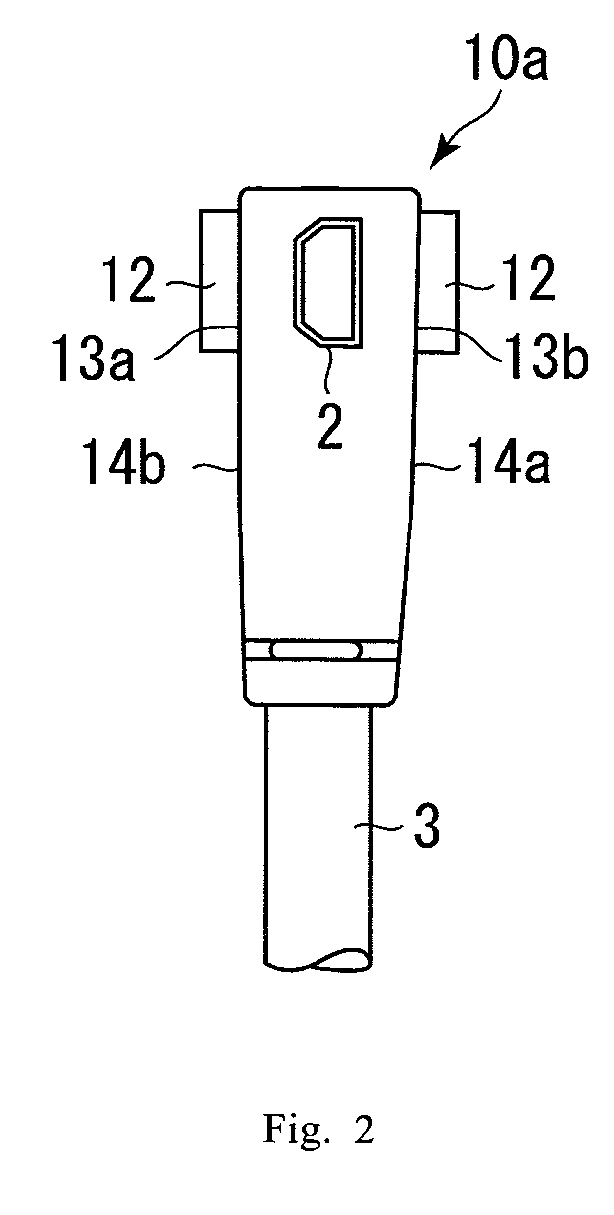
[0032]FIG. 1 and FIG. 2 show an L-shaped connector main body 1 in a state where an inner molded portion has been formed on the connector main body 1 according to the preferred embodiment of the present invention. As shown in these drawings, the connector main body 1 includes a connecting portion 2, and a cable 3 is connected to the connector main body 1. Further, structural members having the same functions as those structures of the prior art L-shaped connector shown in FIG. 5 to FIG. 8 are described using the same reference numerals.

[0033]As shown in FIG. 2, left and right surfaces 14a, 14b of an inner molded portion 10a of the connector of the present embodiment are provided with a pair of positioning portions 12. The positioning portions 12 are formed from a pair of elongated rib-shaped protrusions integrally formed with the inner molded portion 10a,...


PUM


Abstract

A connector includes a connector main body 1 having a metallic electrical connecting portion 2, an inner molded portion 10a provided outside the connector main body and having a pair of protrusions 12 which are integrally formed on the opposite surfaces of the inner molded portion 10a, and an outer molded portion 20a provided outside the inner molded portion so that the protrusions 12 are partially exposed on the outer surface of the outer molded portion 20a. The pair of protrusions 12 protrude toward a pair of metal molds for molding the outer molding portion, respectively.

Description

[0001]This application claims the benefit of Japanese Patent Application No. 2003-392811, filed Nov. 21, 2003.BACKGROUND OF THE INVENTION[0002]1. Field of the Invention[0003]The present invention is related to a connector, and in particular to a connector having a connector main body, an inner molded portion provided outside the connector main body, and an outer molded portion provided outside the inner molded portion.[0004]2. Description of the Prior Art[0005]A prior art L-shaped connector is shown in FIG. 5 to FIG. 8. The process for manufacturing this connector can be divided into three major steps. FIG. 5 shows the finished state of a connector main body 1 in the first step, and this connector main body 1 is constructed mainly from a metallic connecting portion 2, a cable 3, lead wires 4, a metallic holding member 5 and a plastic molded member 6.[0006]In the second step, polypropylene is filled into metal molds for press molding for an inner molded portion to form an inner molde...

Claims


Application Information

Patent Timeline
Patent Type & Authority Patents(United States)
IPC IPC(8): H01R13/58H01R13/50H01R13/658H01R13/6581H01R43/24
CPCH01R13/5845H01R43/24H01R13/6581
Inventor NISHIO, ATSUSHIOHTA, YOSHINORISHINOHARA, YASUHIKO
Owner MITSUMI ELECTRIC CO LTD
Why Eureka
Try Eureka