Device used for precisely grinding turbine disc blade assembly

A technology for precision grinding and turbine blades, which is applied in the direction of grinding workpiece supports, grinding/polishing equipment, grinding machines, etc., and can solve problems such as non-vertical, uneven surface, and inability to guarantee the shape and position tolerance of the outer circular surface of turbine blades. , to achieve precise grinding, save manufacturing costs, and improve high-precision grinding efficiency

Pending Publication Date: 2021-07-23
SICHUAN YAMEI POWER TECH
View PDF0 Cites 0 Cited by
  • Summary
  • Abstract
  • Description
  • Claims
  • Application Information

AI Technical Summary

Problems solved by technology

[0003] The turbine disk in the existing turbine rotor grinding fixture is connected to the support by screws, that is, the turbine disk blade assembly clamps the inner end faces of both sides of the turbine disk through the support to realize the clamping process of the turbine disk blade assembly , but the inner end faces on both sides of the turbine disc are non-machined surfaces, and these two surfaces may have uneven surfaces, or the plane and the outer circular surface of the turbine disc may not be perpendicular, so the clamped turbine disc blade assembly In the process of cylindrical precision grinding, the requirements for the shape and position tolerance of the outer circular surface of the turbine blade cannot be guaranteed

Method used


Image

  • Device used for precisely grinding turbine disc blade assembly
  • Device used for precisely grinding turbine disc blade assembly
  • Device used for precisely grinding turbine disc blade assembly

Examples


Embodiment 1

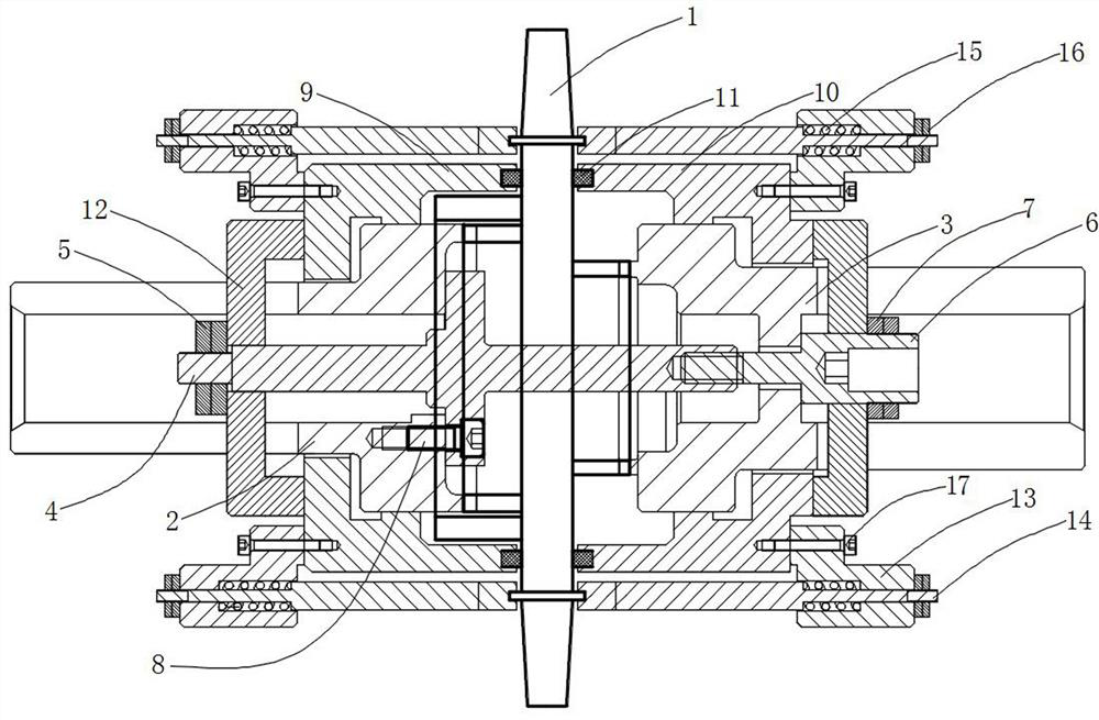
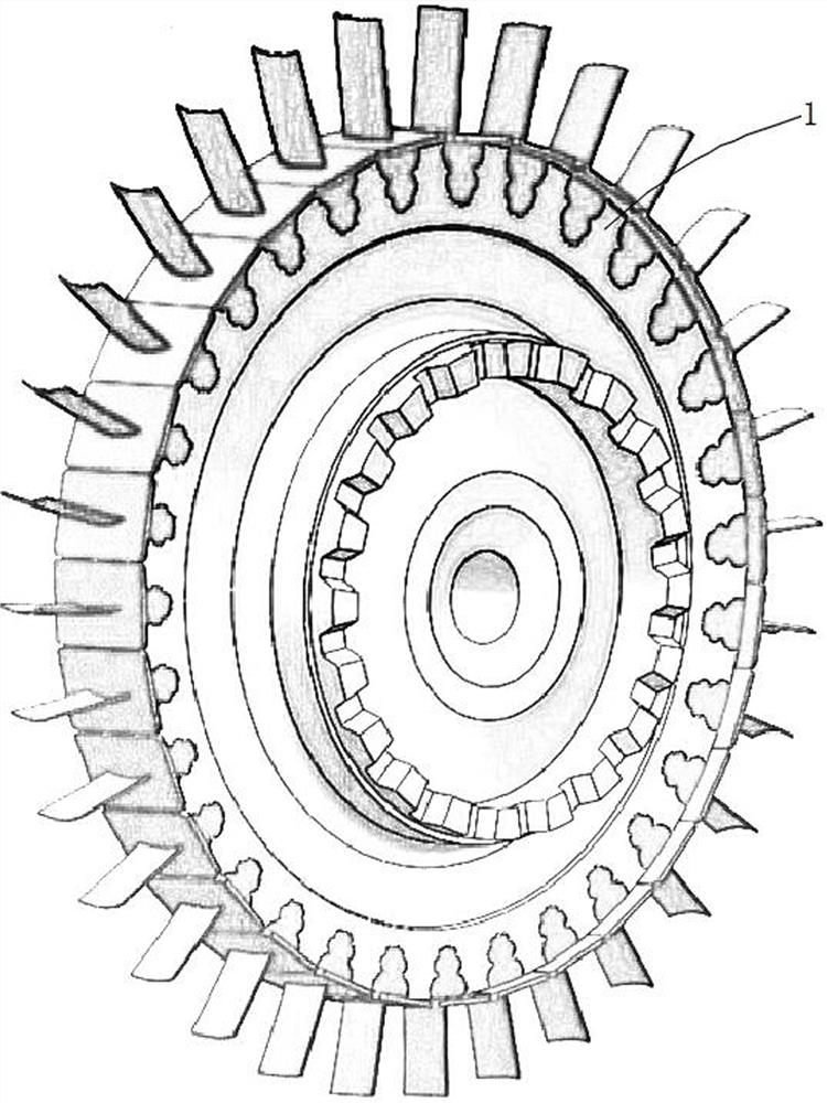
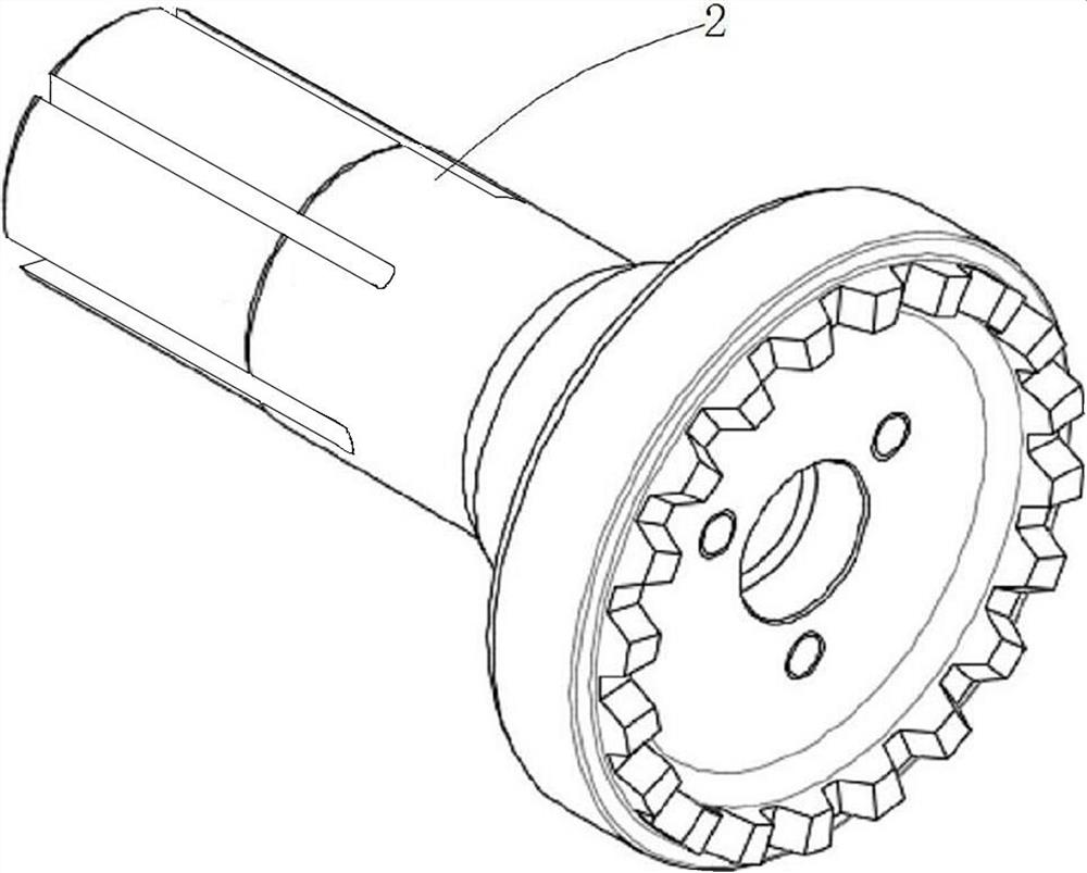
[0030] The main structure of this embodiment, such as Figure 1~4 As shown, the turbine disk blade assembly 1 includes a turbine disk in the middle, turbine blades are evenly distributed on the outer edge of the turbine disk, gear disks are arranged on both sides of the turbine disk, and it is characterized in that it includes a compressed turbine disk blade Assembly 1 and a positioning assembly for positioning it, the positioning assembly includes the first end tooth clamping part 2 on the left side, the second end tooth clamping part 3 on the right side, and the center that runs through the middle of the turbine disk blade assembly 1 Part 4, the right side of the first end tooth clamping part 2 and the left side of the second end tooth clamping part 3 are provided with end teeth, and are respectively highly meshed with the gear discs on both sides of the turbine disc; the center One end of the part 4 is fixedly connected with the first end tooth clamping part 2 through a scr...

Embodiment 2

[0034] In this embodiment, on the basis of the above embodiments, a fixed assembly is further added, such as figure 1 As shown, it also includes a fixing assembly for fixing the positioning assembly, the fixing assembly includes a first fixing sleeve 9 and a second fixing sleeve 10, the first end tooth clamping member 2 is embedded in the first fixing sleeve 9, and the The second end tooth clamping part 3 is embedded in the second fixed sleeve 10, and the first fixed sleeve 9 and the second fixed sleeve 10 are also provided with a compression ring 11 on the side close to the turbine disk blade assembly 1. The tight ring 11 is in close contact with the inner edge of the turbine disk of the turbine disk blade assembly 1 . Other parts of this embodiment are the same as those of the foregoing embodiment, and will not be repeated here.

Embodiment 3

[0036] On the basis of the above-mentioned embodiments, this embodiment further defines the structure of the fixing assembly, such as figure 1 As shown, the ends of the first end tooth clamping part 2 and the second end tooth clamping part 3 are provided with four long through slots extending to the middle of the shaft end, the first end tooth clamping part 2 and the second end tooth clamping part The middle part of the end tooth holder 3 is provided with a compression cross plate 12, and the compression cross plate 12 is inserted into the first end tooth holder 2 or the long through groove at the end of the second end tooth holder 3. The middle part of the end tooth clamping part 2 or the second end tooth clamping part 3, and press the first fixing sleeve 9 or the second fixing sleeve 10;

[0037] The middle part of the compression swash plate 12 embedded in the first end tooth clamping part 2 is penetrated by the central part 4, and the penetrating end of the central part 4 ...


PUM


Abstract

The invention discloses a device used for precisely grinding a turbine disc blade assembly. The turbine disc blade assembly comprises a turbine disc in the middle, turbine blades are uniformly distributed on the outer edge of the turbine disc, and gear discs are arranged on the two sides of the turbine disc. The device comprises a positioning assembly for pressing and positioning the turbine disc blade assembly, the positioning assembly comprises a first end tooth clamping piece, a second end tooth clamping piece and a center piece, and the first end tooth clamping piece and the second end tooth clamping piece are highly engaged with the gear discs on the two sides of the turbine disc correspondingly. One end of the center piece is fixedly connected with the first end tooth clamping piece through a screw, and the other end of the center piece is fixedly connected with the second end tooth clamping piece through a tensioning screw. The end tooth faces of the turbine disc blade assembly are connected in cooperation, the end tooth faces of the two parts are formed through precision machining, a good engagement degree is achieved, it can be guaranteed that axis collineation in the process of precisely grinding the turbine disc blade assembly can be guaranteed, and it is guaranteed that the grinding process of the turbine blades is more precise.

Description

technical field [0001] The invention relates to the technical field of machining, in particular to a device for precision grinding of turbine disc blade assemblies. Background technique [0002] Before assembling the turbine disk blade assembly, it is necessary to precisely grind all the blades on the turbine disk so that the diameter range of the turbine blades reaches the specified value, so as to ensure that the gap between the turbine blades and the stator meets the process requirements. For precision grinding of riveted turbine blades, the grinding circular surface needs to have a high coaxiality with respect to the central axis of the turbine disk, which requires that the end teeth of the turbine blade assembly grinding device and the end teeth of the turbine disk have a high degree of coaxiality. High-precision meshing, and requires that the center hole and end tooth surface of this device also have a high degree of coaxiality. [0003] The turbine disk in the existi...

Claims


Application Information

Patent Timeline
IPC IPC(8): B24B41/06B24B19/14
CPCB24B19/14B24B41/06
Inventor 王一平张东
Owner SICHUAN YAMEI POWER TECH
Why Eureka
Try Eureka