Tin welding machine

A technology of soldering machine and soldering head, applied in welding positions, tin feeding devices, welding equipment, etc., can solve the problems of low production efficiency and unstable welding quality.

Inactive Publication Date: 2018-05-18
WUXI CHANGZHISHENG MACHINERY MFG CO LTD
View PDF9 Cites 6 Cited by
  • Summary
  • Abstract
  • Description
  • Claims
  • Application Information

AI Technical Summary

Problems solved by technology

[0003] In view of the above problems, the present invention provides a soldering machine, which can solve the problem that the existing soldering of electronic devices to the circui...

Method used


Image

  • Tin welding machine
  • Tin welding machine
  • Tin welding machine

Examples


Embodiment Construction

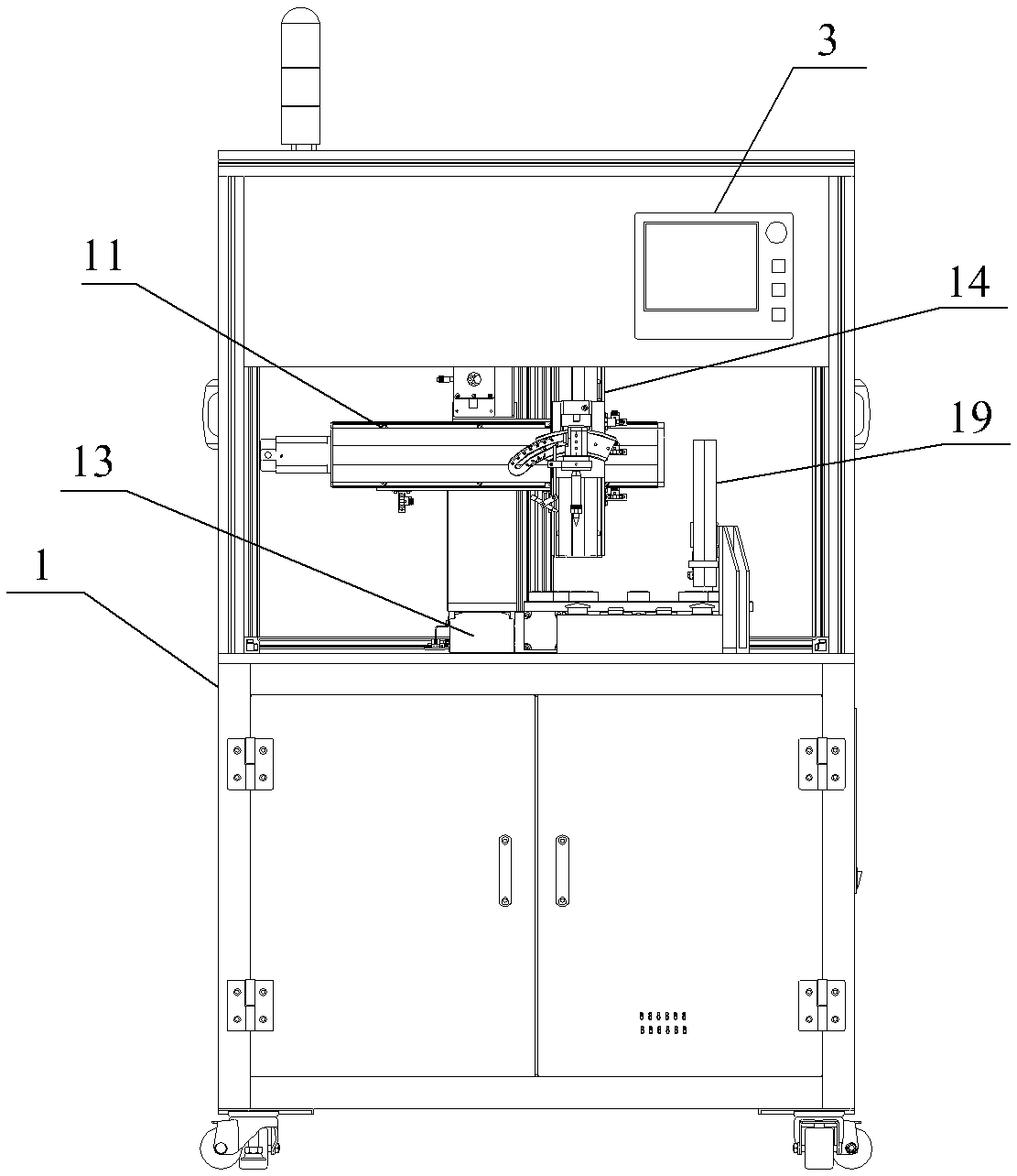
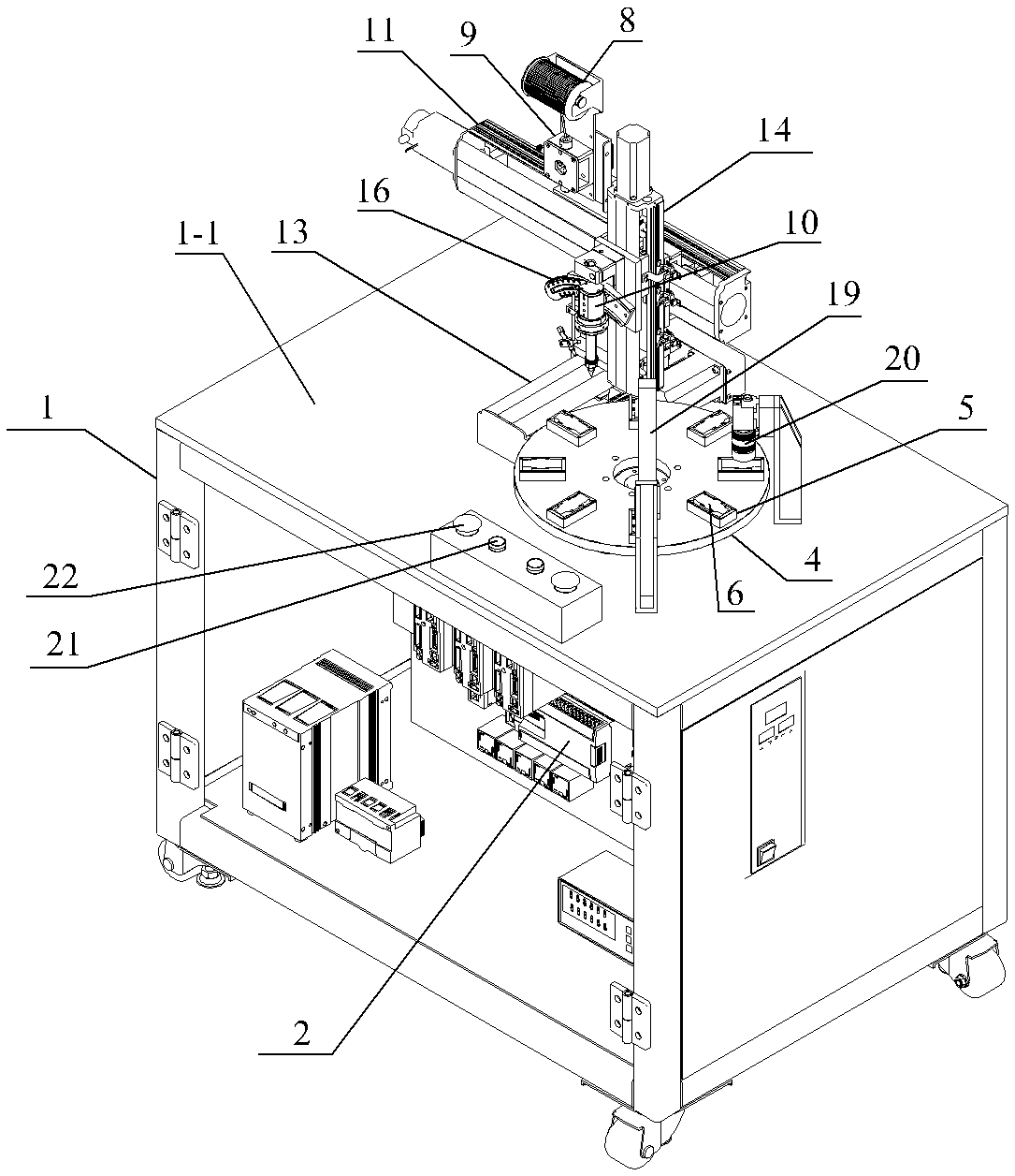
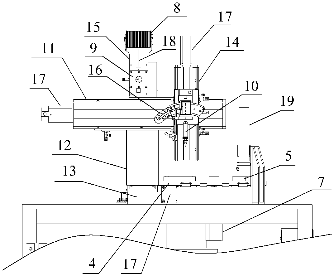
[0020] See Figure 1 to Figure 3 , a kind of soldering machine of the present invention, it comprises frame 1 and is installed in the PLC controller 2 in frame 1, touch screen 3 is installed on frame 1, touch screen 3 is electrically connected with PLC controller 2; There is a horizontal workbench 1-1, on which a solder head support, a turntable 4, an image recognition detection device and a marking device are respectively installed; eight product carriers 5 are evenly distributed along the circumference of the turntable 4, The product carrier 5 is provided with a workpiece groove for positioning the workpiece 6 to be welded. The turntable 4 is driven by the hollow divider to perform index rotation in the horizontal direction. The servo motor 7 of the hollow divider is electrically connected to the PLC controller 2 . The tin wire reel 8, the wire feeder 9 and the solder head 10 are respectively installed on the solder head support. The solder head support includes an X-axis mo...


PUM


Abstract

The invention provides a tin welding machine. The problems that at present, an electronic device is manually welded to a circuit board, product defects need to be manually observed after welding, welding quality is instable, and production efficiency is low can be solved. The tin welding machine comprises a rack and a PLC. Multiple product carriers are evenly distributed and mounted on a rotary disc in the circumferential direction of the rotary disc. Workpiece grooves used for locating to-be-welded workpieces are formed in the product carriers. The rotary disc is driven by a hollow divider todo indexing rotating in the horizontal direction. A servo motor of the hollow divider is in electric control connection with the PLC. A tin wire coiling block, a wire feeder and a tin welding head are mounted on a tin welding head support. The tin welding head, a CCD camera and an ink jet marking machine are sequentially arranged in the rotating direction of the rotary disc and each correspond toone workpiece groove, and the CCD camera and the ink jet marking machine are arranged above the corresponding workpiece grooves correspondingly and are in electric control connection with the PLC.

Description

technical field [0001] The invention relates to the field of welding equipment for assembling printed circuit boards, in particular to a soldering machine. Background technique [0002] After the printed circuit board is manufactured, various electronic devices need to be assembled on the printed circuit board by soldering to make a finished product. The existing soldering process is usually done manually, and requires the cooperation of multiple people. The welding quality is unstable. After welding, the finished product needs to be manually observed for defects, such as whether the surface of the solder point is rough, bridged, soldered or not. Beads, board surface dirt, etc., to screen out defective products, the whole process consumes a lot of manpower, and the efficiency is low. Contents of the invention [0003] In view of the above problems, the present invention provides a soldering machine, which can solve the problem that the existing soldering of electronic dev...

Claims


Application Information

Patent Timeline
IPC IPC(8): B23K3/02B23K3/00B23K3/06B23K3/08
CPCB23K3/00B23K3/026B23K3/063B23K3/08
Inventor 吴坚
Owner WUXI CHANGZHISHENG MACHINERY MFG CO LTD
Why Eureka
Try Eureka