
A welding machine for high-power transformer copper sheet winding and busbar feet
A transformer and high-power technology, which is applied in the field of welding machines for high-power transformer copper sheet windings and bus legs, can solve the problem of high defective product rate, improve production efficiency and product qualification rate, reduce labor costs, and increase economic benefits. Effect
- Summary
- Abstract
- Description
- Claims
- Application Information
AI Technical Summary
Problems solved by technology
Method used
Image

Examples
Embodiment Construction
[0014] The technical solutions of the present invention will be further described in detail below in conjunction with specific embodiments.
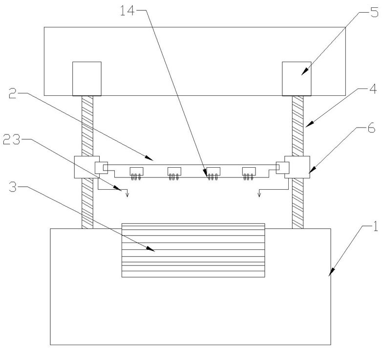
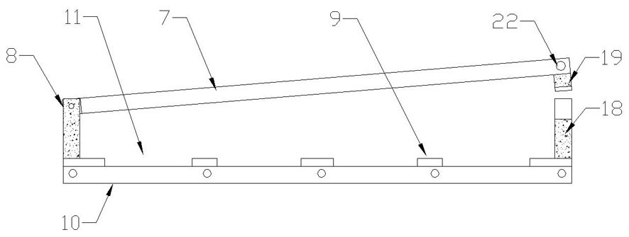
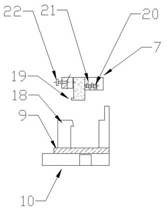
[0015] Please refer to the attached figure 1 , a welding machine for high-power transformer copper sheet windings and busbar feet, including a frame 1, a high-power transformer assembly fixture 2 and a tin furnace 3; there are two lifting screw rods 4 vertically arranged on both sides on the frame 1 , the two lifting screw rods 4 are synchronously driven by the lifting drive motor 5; each lifting screw rod 4 is set with a threaded clamping installation block 6, and the two ends of the high-power transformer assembly jig 2 are respectively clamped on The above-mentioned two threads are clamped on the mounting block 6, and the tin furnace 3 is located directly below the fixture 2 of the high-power transformer assembly; Component jig 2 can perform dipping or lifting movement relative to the solder liquid level of tin furnace 3;
[0016] S...
PUM
 Abstract
Description
Claims
Application Information