Perforating device applicable to steel tubes of different diameters

A drilling device, steel pipe technology, applied in the direction of boring/drilling, toolholder accessories, drilling/drilling equipment, etc., can solve the problems of inability to adjust, steel pipe vibration, breakage, etc., to improve accuracy and stability Performance, improve work efficiency, improve the effect of stability

Active Publication Date: 2018-05-25
四川省建筑机械化工程有限公司
View PDF7 Cites 2 Cited by
  • Summary
  • Abstract
  • Description
  • Claims
  • Application Information

AI Technical Summary

Problems solved by technology

[0002] The positioning and locking of circular steel pipes during the drilling process is very important, because inaccurate positioning will lead to the deviation of the hole center, and insecure locking will also cause the hole center to deviate due to vibration during the drilling process. Mass production requires not only accurate drilling but also fast positioning. At present, the cylinder is mainly used to achieve fast locking, but this method can only ensure the locking of the chuck part to the steel pipe, and the locking at this position cannot guarantee the fast locking during the drilling process. The stability of the entire steel pipe in the hole can easily cause the steel pipe in the drilling to vibrate. If the degree of locking is not controlled, the drill bit is easy to wear and break, the hole surface is rough, the hole diameter is too large, the hole shape is not round or inclined to one side, etc. In addition, the locking device and position adjustment device of traditional steel pipe drilling processing equipment have a single structure, which cannot be adjusted according to steel pipes of different diameters.

Method used


Image

  • Perforating device applicable to steel tubes of different diameters
  • Perforating device applicable to steel tubes of different diameters
  • Perforating device applicable to steel tubes of different diameters

Examples


Embodiment Construction

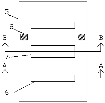
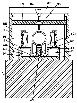
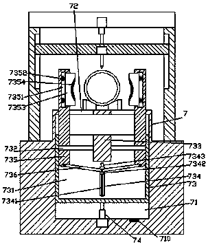
[0021] like figure 1 , figure 2 , image 3 and Figure 4 As shown, a punching device suitable for steel pipes of different diameters according to the present invention includes a base 5, a locking device 7 is provided on the top end surface of the base 5, and a locking device 7 is arranged on the front and rear sides of the locking device 7. The symmetrically arranged rolling adjustment device 6, the base 5 between the locking device 7 and the rolling adjustment device 6 on the rear side is provided with a punching frame 8, and each of the rolling adjustment devices 6 has a A first slide groove 64 and a second slide groove 61 arranged symmetrically on the left and right are provided, a partition plate 62 is arranged between the first slide groove 64 and the second slide groove 61, and the first slide groove 64 and the second slide groove 61 The second sliding groove 61 is provided with a supporting member 63, and the supporting member 63 on the left and right sides is prov...


PUM


Abstract

The invention discloses a perforating device applicable to steel tubes of different diameters. The perforating device comprises a base. The end face of the top of the base is provided with a clampingdevice and rolling adjustment devices, wherein the rolling adjustment devices are arranged at the front side and the rear side of the clamping device in a symmetrical manner. A perforating rack is arranged at the position, between the clamping device and the rolling adjustment device at the rear side, on the base. Each rolling adjustment device is internally provided with a first sliding groove and a second sliding groove which are symmetrical in the left-right direction. A partition plate is arranged between each first sliding groove and the corresponding second sliding groove. The first sliding grooves and the second sliding grooves are each internally provided with a bearing component. Rolling wheels with the conical surface sides being opposite are arranged in the bearing components atthe left side and the right side. The clamping device is internally provided with an ascending-and-descending sliding cavity, wherein the ascending-and-descending sliding cavity communicates with theportion, at the bottom of the clamping device, inside the base. The ascending-and-descending sliding cavity is internally provided with an ascending-and-descending sliding component. Through groovesare symmetrically formed in the left side and the right side of the top of the clamping device. The ascending-and-descending sliding component is internally provided with a driving sliding cavity. Theperforating device is simple in structure and convenient to operate, and perforating precision and steadiness are improved.

Description

technical field [0001] The invention relates to the technical field of steel pipe processing, in particular to a punching device suitable for steel pipes with different diameters. Background technique [0002] The positioning and locking of circular steel pipes during the drilling process is very important, because inaccurate positioning will lead to the deviation of the hole center, and insecure locking will also cause the hole center to deviate due to vibration during the drilling process. Mass production requires not only accurate drilling but also fast positioning. At present, the cylinder is mainly used to achieve fast locking, but this method can only ensure the locking of the chuck part to the steel pipe, and the locking at this position cannot guarantee the fast locking during the drilling process. The stability of the entire steel pipe in the hole can easily cause the steel pipe in the drilling to vibrate. If the degree of locking is not controlled, the drill bit is...

Claims


Application Information

Patent Timeline
Patent Type & Authority Applications(China)
IPC IPC(8): B23B41/00
CPCB23B41/00B23B2215/72
Inventor 郭超杰
Owner 四川省建筑机械化工程有限公司
Why Eureka
Try Eureka