Ultra-high-efficiency energy-saving rare earth permanent-magnet synchronous motor

A rare-earth permanent magnet and synchronous motor technology, which is applied to synchronous machines, synchronous motors with stationary armatures and rotating magnets, and parts of synchronous machines, can solve problems such as high cost, unreliable connection, and inaccurate adjustment. Achieve the effect of low production cost, good self-locking effect and high adjustment precision

Active Publication Date: 2018-08-28
杭州奇虎节能技术有限公司
View PDF7 Cites 2 Cited by
  • Summary
  • Abstract
  • Description
  • Claims
  • Application Information

AI Technical Summary

Problems solved by technology

For the high-speed rotating rotor, it is difficult to achieve the required accuracy by screwing the balance screw. The welding method will have an adverse effect on the rotor. The method of removing material is irreversible and has a certain impact on the strength of the rotor.
Secondly, at present, most of the dynamic balance tests and corrections of the rotor are carried out at normal temperature, while the rotor usually runs at a higher temperature for a long time, and the change of temperature will often cause new imbalances in the rotor, especially when the speed is 3000rpm For the above high-speed motors, even a small amount of unbalance will cause the machine vibration of the motor, and have a serious adverse effect on the running quality and service life of the motor
[0004] The traditional rotor balance structure balances the weight by opening small holes on one side of the counterweight. This balance method has disadvantages such as inconvenient control, small control range, and inaccurate adjustment.
However, the traditional weight-increasing structure has the disadvantages of unreliable connection and the inability to adjust the weight of specific positions
[0005] At the same time, the traditional motor junction box is sealed with a gasket between the box cover and the box body. When bolts are used to connect the box cover and the box body, the edge of the gasket installed in this way is exposed to the outside, which is easy to be damaged. The corrosion of the surrounding environment reduces its service life, causing smoke and moisture to enter the junction box and cause short circuit of the motor; at the same time, the metal box cover has disadvantages such as poor corrosion resistance, inconvenient processing, and high cost.

Method used


Image

  • Ultra-high-efficiency energy-saving rare earth permanent-magnet synchronous motor
  • Ultra-high-efficiency energy-saving rare earth permanent-magnet synchronous motor
  • Ultra-high-efficiency energy-saving rare earth permanent-magnet synchronous motor

Examples


Embodiment 1

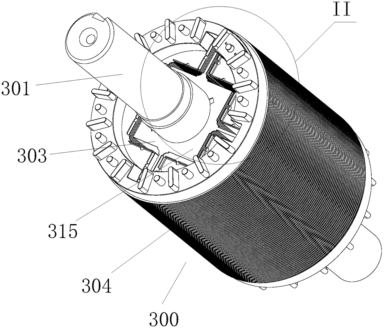
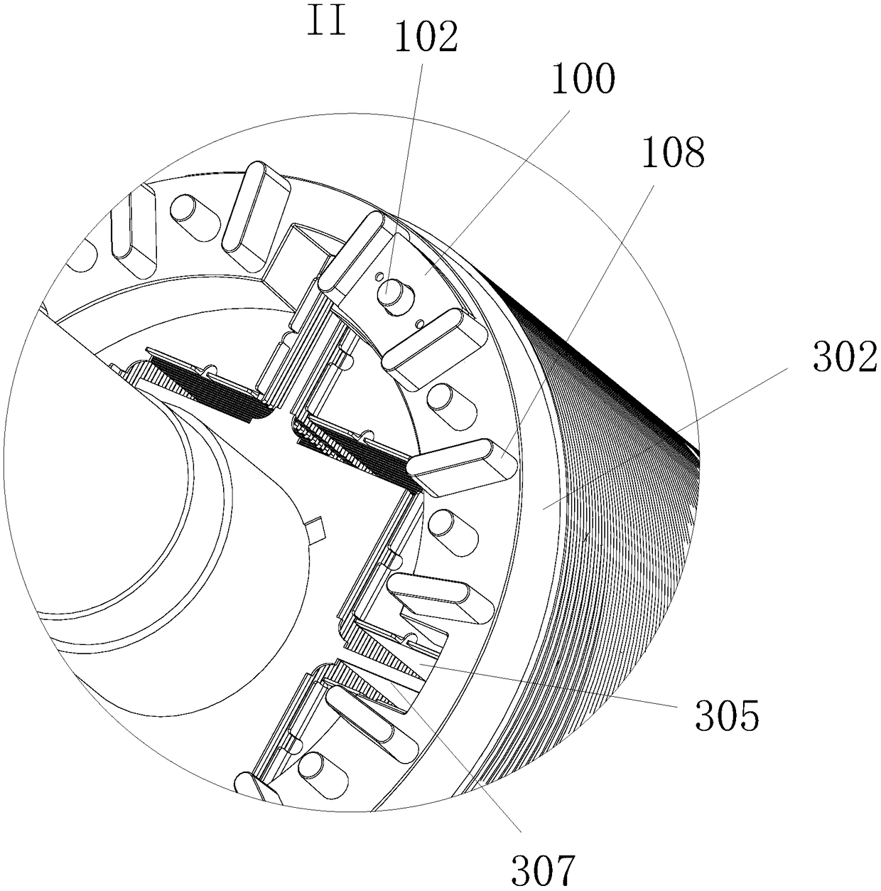
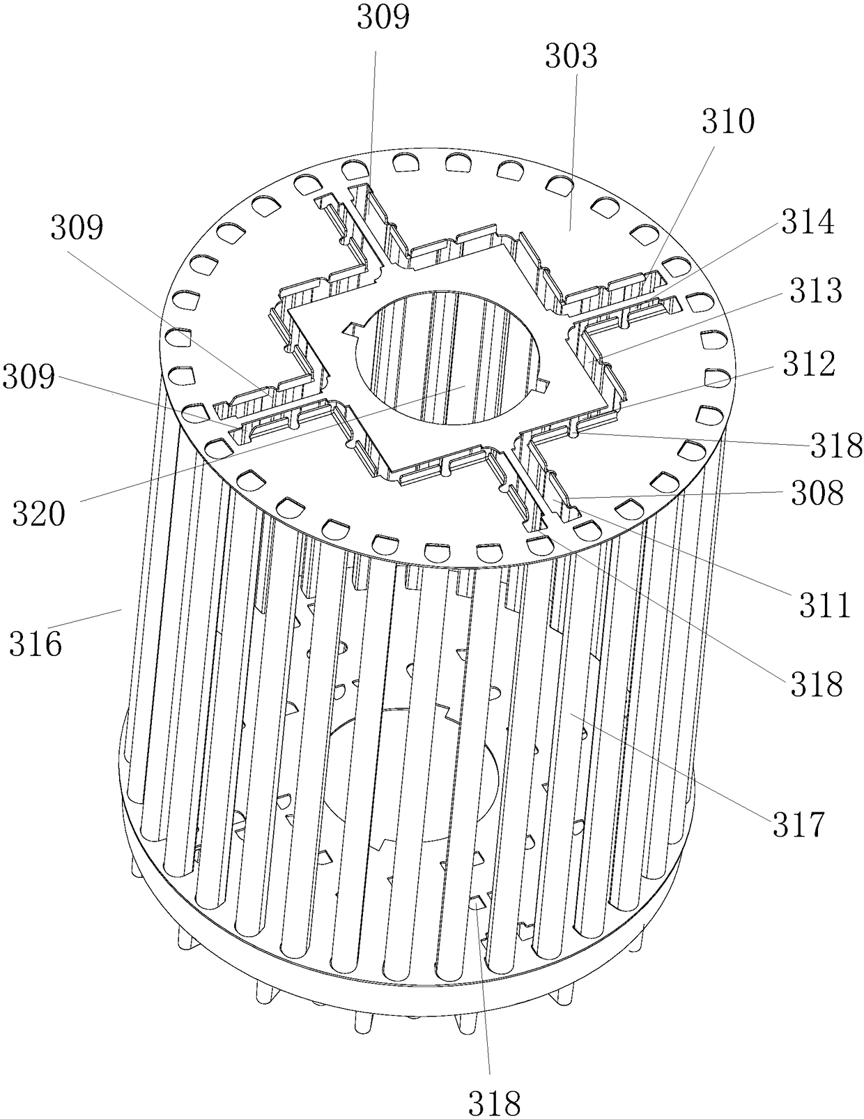
[0036] Such as Figure 1 to Figure 12 As shown, the ultra-ultra-high-efficiency energy-saving rare earth permanent magnet synchronous motor includes a casing 150. A rotor body 300 is arranged inside the casing 150. The rotor body 300 includes a rotating shaft 301. Short-circuit rings 302 are arranged at both ends of the rotor body 300. The short-circuit rings 302 A stopper 303 is fastened between the rotor body 300. The rotor body 300 includes a rotor core 304. The rotor core 304 and the stopper 303 are sleeved on the rotating shaft 301. The middle part of the rotor core 304 is provided with a groove that runs through both ends. 305, a magnetic steel is embedded in the cavity 305, and the stopper 303 is fixed on both ends of the rotor core 304 through the short-circuit ring 302 to seal and limit the magnetic steel; the stopper 303 at one end is provided with a shape similar to the opening shape of the cavity 305 1. The filling port 307 corresponding to the position, the edge o...


PUM


Abstract

The invention, which relates to the field of electric motors, discloses an ultra-high-efficiency energy-saving rare earth permanent-magnet synchronous motor comprising a rotor body (300). The rotor body (300) includes a rotor iron core (304); and the rotor iron core (304) and separation blades (303) sleeve a rotating shaft (301). A slot cavity (305) penetrating the two ends of the rotor iron core(304) is formed in the middle of the rotor iron core (304); a magnetic steel is embedded into the slot cavity (305); the separation blades (303) cover the two ends of the rotor iron core (304); and the two ends of the magnetic steel are abutted against the inner sides of the separation blades (303). A filler opening (307) having the shape and position corresponding to those of the slot cavity (305) is formed in the separation blade (303) at at least one end; and bendable sealing plates (308) are arranged at the edge of the filler opening and clamp and seal the filler opening (307) by bending.The motor has advantages of great convenience in mounting, accurate and reliable magnetic steel positioning, good dustproof and waterproof effects, reasonable balance weight effect, and great easinessin adjustment and the like; and usage of a curing agent is avoided; and the cooling effect is good.

Description

technical field [0001] The invention relates to the field of permanent magnet motors, in particular to an ultra-super-high-efficiency energy-saving rare-earth permanent magnet synchronous motor. Background technique [0002] The existing permanent magnet rotor has disadvantages such as small starting torque and poor heat dissipation due to unreasonable structural design of the magnetic circuit and silicon steel sheets and poor precision. Moreover, during the installation of the magnets, the magnets are relatively strong, which easily causes the magnets to pop out, and the magnets are easily cracked, so screws cannot be used for positioning, which makes the installation of the magnets difficult and the installation efficiency low. In the prior art, a cavity is provided in the rotor core body to contain the magnet, and the magnet is then fixed by a fixative. Although this method is simple in operation, there is a problem that the curing agent will appear after the motor runs h...

Claims


Application Information

Patent Timeline
Patent Type & Authority Applications(China)
IPC IPC(8): H02K21/14H02K21/46H02K21/02H02K1/28H02K7/04H02K5/22H02K5/10
Inventor 周文彪张志军徐传坤
Owner 杭州奇虎节能技术有限公司
Why Eureka
Try Eureka