Power take-off ECU control system with clutch and using method thereof

A control system with clutch technology, applied in the direction of clutches, fluid-driven clutches, non-mechanical drive clutches, etc., can solve problems such as the inability to realize free shifting, achieve good prompting effects, avoid operating errors, and have high safety effects

Active Publication Date: 2018-09-04
DONGFENG COMML VEHICLE CO LTD
View PDF6 Cites 2 Cited by
  • Summary
  • Abstract
  • Description
  • Claims
  • Application Information

AI Technical Summary

Problems solved by technology

[0005] The purpose of the present invention is to overcome the defects and problems existing in the prior art that free shifting cannot be realized under driving power taking conditions, and to provide a power taking off with clutch that can realize free shifting under driving power taking conditions. Device ECU control system and using method thereof

Method used


Image

  • Power take-off ECU control system with clutch and using method thereof

Examples


Embodiment 1

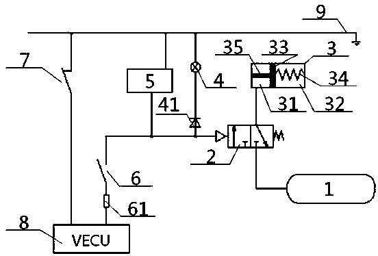
[0037] see figure 1 , a power take-off ECU control system with a clutch, including VECU8, clutch, clutch switch 7, power take-off switch 6, power take-off, power take-off solenoid valve 2 and air storage tank 1, the air outlet of the air storage tank 1 and The intake ports of the force-taking electromagnetic valve 2 are communicated, and the clutch cylinder 3 in the clutch includes an outer chamber 31, an inner chamber 32 and a clutch piston 33 between the two, and one side of the clutch piston 33 is connected by a clutch spring 34 is connected with the right side wall of the inner chamber 32, the other side of the clutch piston 33 is connected with one end of the connecting shaft 35, the other end of the connecting shaft 35 extends outside the outer chamber 31, and is connected with the power take-off The input end is connected to drive; the outer chamber 31 is connected to the air storage tank 1 through the power take-off solenoid valve 2, and the control end of the power ta...

Embodiment 2

[0040] Basic content is the same as embodiment 1, the difference is:

[0041] The junction between the power take-off switch 6 and the control end of the power take-off solenoid valve 2 is connected to the grounding wire 9 via the multifunctional buzzer 5 and the indicator light 4 connected in parallel.

[0042] When the power is taken normally, the multifunctional buzzer 5 and the indicator light 4 are energized, the multifunctional buzzer 5 makes a sound, and the indicator light 4 lights up to remind the operator that the power is being taken off; When shifting gears, the multi-function buzzer 5 and the indicator light 4 lose power, the multi-function buzzer 5 does not sound, and the indicator light 4 does not light.

Embodiment 3

[0044] Basic content is the same as embodiment 2, the difference is:

[0045] The junction between the power take-off switch 6 and the control end of the power take-off solenoid valve 2 is connected to the anode of a diode 41 , and the cathode of the diode 41 is connected to the ground wire 9 via the indicator light 4 .

[0046] During normal power take-off, after the power take-off switch 6 and the clutch switch 7 are closed, only unidirectional current flows through the diode 41 to prevent the power take-off from malfunctioning.


PUM


Abstract

The invention relates to a power take-off ECU control system with a clutch. The system comprises a VECU, a power take-off, the clutch, a clutch switch, a power take-off switch, a power take-off electromagnetic valve and a gas storage tube, the gas storage tube is communicated with a clutch air cylinder through the power take-off valve, a connecting shaft in the clutch air cylinder is in driving connection with the power take-off, the control end of the power take-off valve is connected with the output end of the VECU through the power take-off switch, the input end of the VECU is connected with a grounding wire through the clutch switch, the part between the grounding wire and the intersection position of the power take-off switch and the power take-off electromagnetic valve is in parallelconnection with a multifunctional buzzer and a dashboard indicating lamp, and when the system is used, whether or not the power take-off electromagnetic valve is electrified is controlled by the clutch switch so as to control whether or not air is taken into the clutch air cylinder to further control whether or not the power take-off is operated. By means of the system, not only can freely gear switching be achieved under the working condition of driving power take-off, but also the prompting effect is better, and the safety performance is higher.

Description

technical field [0001] The invention relates to a control system of a power take-off, in particular to an ECU control system of a power take-off with a clutch and a method for using the same, and is particularly suitable for realizing free gear shifting under the driving power take-off working condition. Background technique [0002] The power take-off of the main box of the existing commercial vehicle gearbox takes power from the intermediate shaft of the gearbox, and the transmission route of the power take-off is the engine, the clutch, the first shaft of the transmission, the intermediate shaft of the transmission, and the power take-off is output through the flange or the spline. Under driving power take-off conditions (such as sprinklers, washing and sweeping vehicles), when the power take-off is working, the load always acts on the first shaft of the transmission. At this time, it is impossible to shift gears. The driver can only stop repeatedly - turn off the power ta...

Claims


Application Information

Patent Timeline
Patent Type & Authority Applications(China)
IPC IPC(8): B60K25/06B60Q9/00F16D25/12F16D25/0638
CPCF16D25/0638F16D25/14B60K25/06B60Q9/00F16D2025/081B60K2370/161
Inventor 蔚连浩张常武赵晶杨帆王超叶婷何秀校王峰张凯丽
Owner DONGFENG COMML VEHICLE CO LTD
Why Eureka
Try Eureka