Power takeoff hydraulic electric control system with clutch and use method of system

An electrical control system and technology with a clutch, applied in clutches, fluid-driven clutches, non-mechanical-driven clutches, etc., can solve problems such as the inability to achieve free shifting

Pending Publication Date: 2018-08-28
DONGFENG COMML VEHICLE CO LTD
View PDF6 Cites 1 Cited by
  • Summary
  • Abstract
  • Description
  • Claims
  • Application Information

AI Technical Summary

Problems solved by technology

[0005] The purpose of the present invention is to overcome the defects and problems existing in the prior art that free shifting cannot be realized under driving power taking conditions, and to provide a power taking off with clutch that can realize free shifting under driving power taking conditions. Hydraulic and electrical control system of the device and its application method

Method used


Image

  • Power takeoff hydraulic electric control system with clutch and use method of system
  • Power takeoff hydraulic electric control system with clutch and use method of system
  • Power takeoff hydraulic electric control system with clutch and use method of system

Examples


Embodiment 1

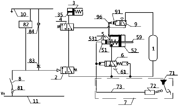
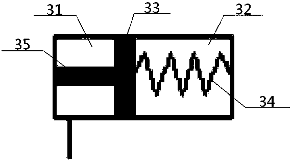
[0046] see figure 1 - Figure 4 , a hydraulic electrical control system for a power take-off with a clutch, including a bypass valve 9, a power take-off control valve 4, a clutch, a booster 5, a booster control valve 6, a power take-off, a power take-off solenoid valve 2, and an air storage tank 1 and the hydraulic source 7, the air outlet of the air reservoir 1 communicates with the air inlet of the power take-off solenoid valve 2, and the clutch cylinder 3 in the clutch includes an outer chamber 31, an inner chamber 32 and a The clutch piston 33, one side of the clutch piston 33 is connected with the right side wall of the inner chamber 32 through the clutch spring 34, the other side of the clutch piston 33 is connected with one end of the connecting shaft 35, and the other end of the connecting shaft 35 Extending to the outside of the outer chamber 31, and drivingly connected to the input end of the power take-off; the bypass valve 9 includes a force-bearing control end 91...

Embodiment 2

[0049] Basic content is the same as embodiment 1, the difference is:

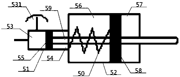
[0050] The booster 5 includes a booster cylinder 51 and a booster cylinder 52, the booster cylinder 51 includes an active oil chamber 53, a follower oil chamber 54 and a cylinder piston 55 between them, and the booster cylinder 52 includes an active air chamber 56 , the cylinder piston 58 between the follower air chamber 57 and the two, and the side near the booster cylinder 52 on the oil cylinder piston 55 is connected with an end of the thrust rod 59, and the other end of the thrust rod 59 passes through the follower oil chamber 54, the active Air chamber 56, cylinder piston 58, and follower air chamber 57 extend to the outside of booster cylinder 52. The position in the active air chamber 56 on the thrust rod 59 is covered with a cylinder spring 50, and one end of the cylinder spring 50 is connected to the active air chamber 56. The left cavity wall of the cylinder is connected, and the other end of the ...

Embodiment 3

[0053] Basic content is the same as embodiment 1, the difference is:

[0054] The hydraulic source 7 includes a hydraulic pipeline 73, a master cylinder 72 and a clutch pedal 71. The driving end of the master cylinder 72 is located directly below the clutch pedal 71, and the output end of the master cylinder 72 is connected to the power cylinder 51 through the hydraulic pipeline 73 , and the control ends of the booster control valve 6 are connected.

[0055] The opening of the hydraulic source 7 refers to: stepping on the clutch pedal 71 to open the driving end of the master cylinder 72, so that the output end of the master cylinder 72 outputs hydraulic oil to the hydraulic pipeline 73; the closing of the hydraulic source 7 refers to: loosening Open the clutch pedal 71 to close the driving end of the master cylinder 72, so that the output end of the master cylinder 72 no longer outputs hydraulic oil.


PUM


Abstract

A power takeoff hydraulic electric control system with a clutch comprises a bypass valve, a booster, the clutch, a power takeoff, a power takeoff control valve, a power-assisted control valve, a hydraulic source, a power takeoff switch, a power takeoff solenoid valve and an air reservoir. The air reservoir sequentially passes the power takeoff solenoid valve and the power takeoff control valve andthen is communicated with a clutch cylinder, a connecting shaft in the clutch cylinder is in driving connection with the power takeoff, a control end of the power takeoff solenoid valve is controlledto be powered on by the power takeoff switch, a control end of the power takeoff control valve is controlled to acquire gas or not by the hydraulic source through the power-assisted control valve, the booster and the bypass valve, and a multifunctional buzzer and a meter lamp are parallelly connected between the junction of the power takeoff switch and the power takeoff solenoid valve and a grounding wire. By the design, free gear shifting under driving power takeoff conditions can be realized, prompt effects are good, hydraulic pressure and air pressure are sufficiently used for control, andthe system is high in popularization and application value and strong in safety.

Description

technical field [0001] The invention relates to a control system of a power take-off, in particular to a hydraulic and electrical control system of a power take-off with a clutch and a method for using the same, and is particularly suitable for realizing free gear shifting under the power take-off working condition of a vehicle. Background technique [0002] The power take-off of the main box of the existing commercial vehicle gearbox takes power from the intermediate shaft of the gearbox, and the transmission route of the power take-off is the engine, the clutch, the first shaft of the transmission, the intermediate shaft of the transmission, and the power take-off is output through the flange or the spline. Under driving power take-off conditions (such as sprinklers, washing and sweeping vehicles), when the power take-off is working, the load always acts on the first shaft of the transmission. At this time, it is impossible to shift gears. The driver can only stop repeatedl...

Claims


Application Information

Patent Timeline
Patent Type & Authority Applications(China)
IPC IPC(8): B60K25/06B60Q9/00F16D25/12F16D25/0638
CPCF16D25/0638F16D25/14B60K25/06B60Q9/00F16D2025/081B60K2370/161
Inventor 蔚连浩何秀校王峰李朝富张光哲黄遵国张叶青廖宜剑王诚诚
Owner DONGFENG COMML VEHICLE CO LTD
Why Eureka
Try Eureka