Brake pedal device for electromechanical brake system

An electronic mechanical brake and brake pedal technology, applied to the online control brake system and the field of brake pedal force feedback, can solve the problems of inaccurate feedback of braking force status, hydraulic feedback lag, and feedback insensitivity, etc., to achieve a compact and concise structure , easy pre-installation, good economical effect

Pending Publication Date: 2018-09-14
LIAOCHENG UNIV
View PDF0 Cites 3 Cited by
  • Summary
  • Abstract
  • Description
  • Claims
  • Application Information

AI Technical Summary

Problems solved by technology

The above two devices have their own disadvantages. The former one has a complex structure, many parts, and has the disadvantages of hydraulic feedback hysteresis, and when the pedal is continuously stepped on, the feedback is not sensitive due to the throttling effect of the solenoid valve hole.
Although the latter device has a simple structure, the structure cannot accurately feed back the braking force condition.

Method used


Image

  • Brake pedal device for electromechanical brake system
  • Brake pedal device for electromechanical brake system
  • Brake pedal device for electromechanical brake system

Examples


Embodiment

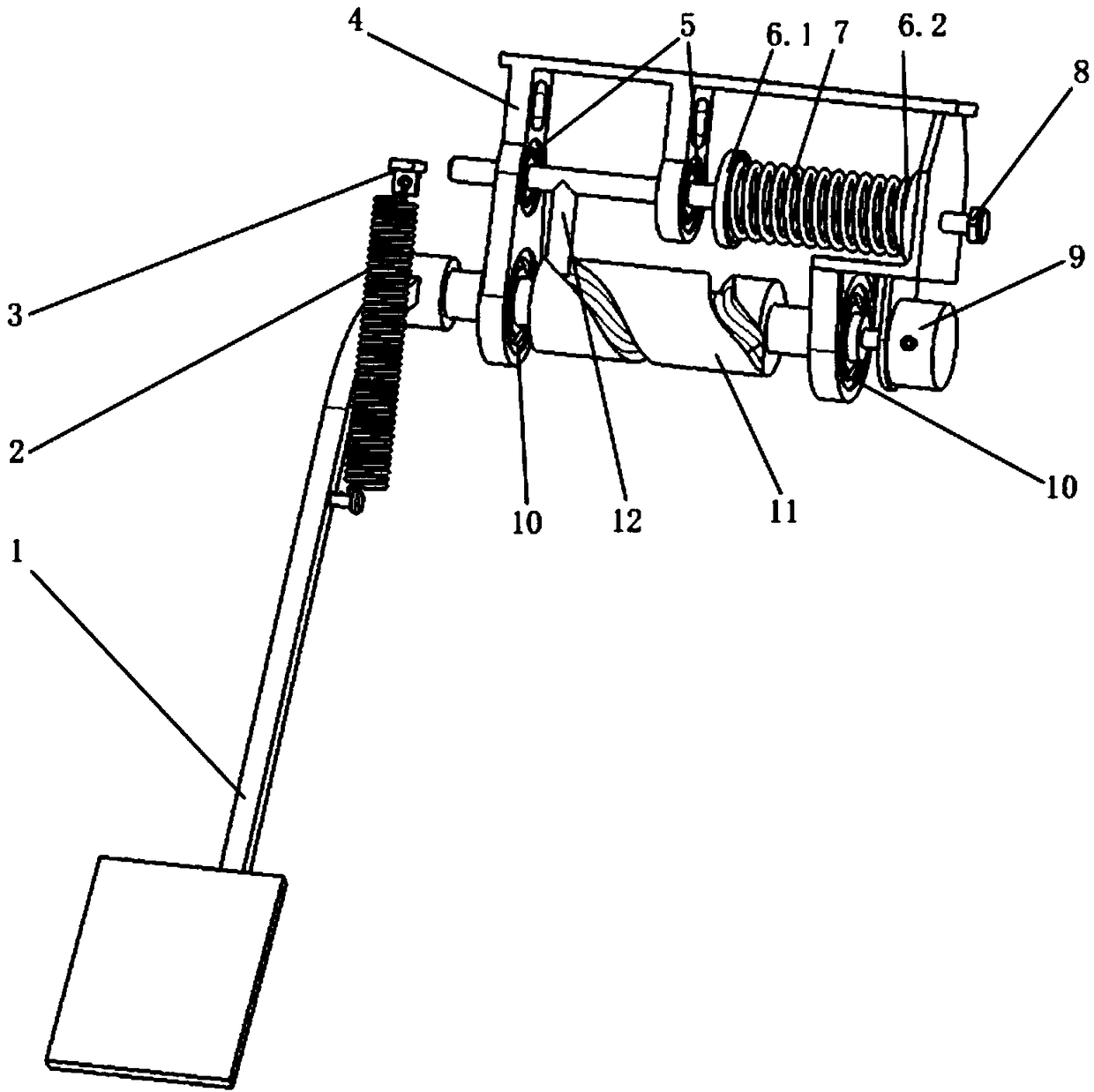
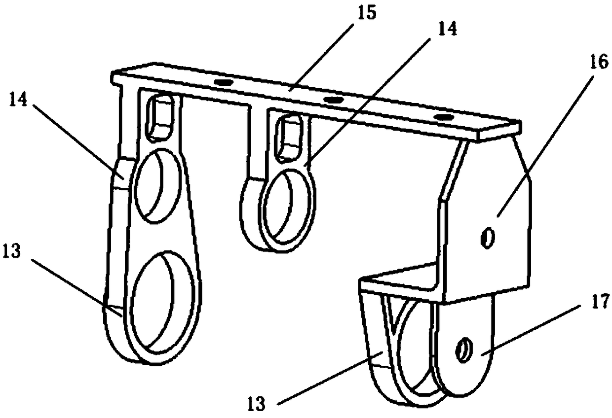
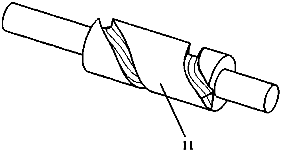
[0027] A pedal device for an electromechanical brake, the structure of which is as follows figure 1 , 3 , shown in 4, including support 4, cylindrical cam 11, push rod 12, pedal force simulation spring 7, brake pedal 1, adjusting bolt 8, angular displacement sensor 9, described pedal force simulation spring 7 passes through the first spring seat 6.1 and the second spring seat 6.2 are installed on the support 4, the cylindrical cam 11 is installed on the support 4 through the cam bearing 10, and the push rod 12 is installed on the support through the push rod bearing 5 4, the brake pedal 1 is installed on one end of the cylindrical cam 11 through a spline, the angular displacement sensor 9 is installed on the other end of the cylindrical cam 11, and one end of the return spring 2 is installed on the brake pedal 1, The other end is fixed on the automobile body through the return spring seat 3, the surface of the cylindrical cam 11 is provided with a cylindrical cam groove, the ...


PUM


Abstract

The invention discloses a brake pedal device for an electromechanical brake system. The brake pedal device comprises a support, a cylinder cam, a T-shaped pushing rod, a pedal force simulation spring,a brake pedal and an angular displacement sensor, the pedal force simulation spring is mounted on the support through a first spring seat and a second spring seat, the cylinder cam is mounted on thesupport through a cam bearing, the pushing rod is mounted on the support through a pushing rod bearing, the brake pedal is mounted at one end of the cylinder cam through a spline, the angular displacement sensor is mounted at the other end of the cylinder cam, one end of a reset spring is mounted on the brake pedal, the other end of the reset spring is fixed onto an automobile body through a resetspring seat, a cylinder cam groove is formed in the surface of the cylinder cam, and the pushing rod is matched with the cylinder cam groove. According to the brake pedal device, a driver can feel real-time and accurate brake conditions of an automobile through the brake pedal, and the brake pedal device is simple in structure and convenient to install and adjust.

Description

technical field [0001] The invention belongs to the technical field of brake systems under automobile engineering, in particular to brake systems by wire, and relates to a brake pedal force feedback technology for an electromechanical brake system. Background technique [0002] The control-by-wire technology is one of the four core technologies (precise positioning, path planning, environment perception, and control-by-wire execution) of intelligent and unmanned vehicles. The brake-by-wire system is an important part of the vehicle-by-wire system. The brake-by-wire system is currently divided into electro-hydraulic brake system (EHB) and electro-mechanical brake system (EMB). The electro-mechanical brake system uses electric energy as the energy source, and the driver's braking intention generates an electric signal through the brake pedal unit. The data is transmitted to the brake system controller through the data line, and the controller issues instructions to make the mo...

Claims


Application Information

Patent Timeline
Patent Type & Authority Applications(China)
IPC IPC(8): B60T8/40B60T7/06
CPCB60T8/409B60T7/06
Inventor 陈峥峰马振强王超
Owner LIAOCHENG UNIV
Why Eureka
Try Eureka