Cylindrical cell battery pack packaging structure suitable for bearing large current

A packaging structure, battery pack technology, applied in the direction of cylindrical shell cells/batteries, battery pack components, secondary batteries, etc. Problems such as poor heat dissipation, to achieve the effect of firm spot welding, good spot welding effect and compact structure of the battery

Pending Publication Date: 2018-09-14
四川众联航泰科技有限公司
View PDF0 Cites 2 Cited by
  • Summary
  • Abstract
  • Description
  • Claims
  • Application Information

AI Technical Summary

Problems solved by technology

[0002] Cylindrical batteries have been widely promoted and used due to their well-known advantages. At present, the most common series-parallel connection method of cylindrical batteries is single energy storage spot welding. The disadvantage of this method is that if the bracket is not used, the heat dissipation of the battery pack is not good. Well, if the bracket is used, the after-sales maintenance and recycling of the single battery is a big problem, and the pure nickel strip is spot-welded. In order to meet the high-current work, it is necessary to spot-weld multiple nickel strips, the production efficiency is low, and the same battery The core needs to withstand multiple spot welding pressures, which affects the performance of the single cell. Moreover, in order to match the welding effect of the battery cell, sometimes larger or thicker parts cannot be selected, resulting in the inability to meet the design requirements for excessive current. not broad

Method used


Image

  • Cylindrical cell battery pack packaging structure suitable for bearing large current
  • Cylindrical cell battery pack packaging structure suitable for bearing large current
  • Cylindrical cell battery pack packaging structure suitable for bearing large current

Examples


Embodiment Construction

[0028] The technical solutions of the present invention will be clearly and completely described below in conjunction with the embodiments. Apparently, the described embodiments are only some of the embodiments of the present invention, not all of them. Based on the embodiments of the present invention, all other embodiments obtained by those skilled in the art without making creative efforts belong to the protection scope of the present invention.

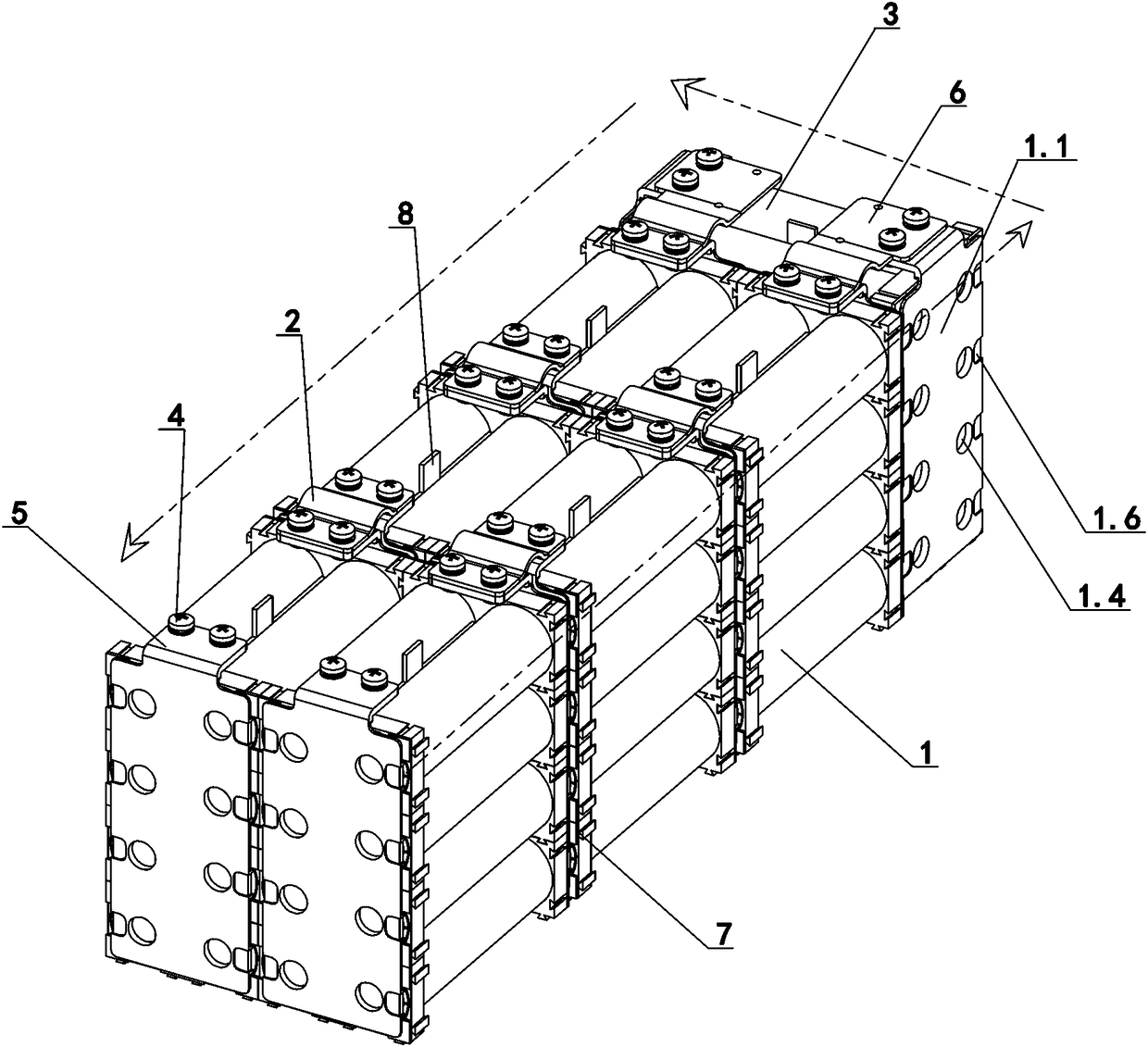
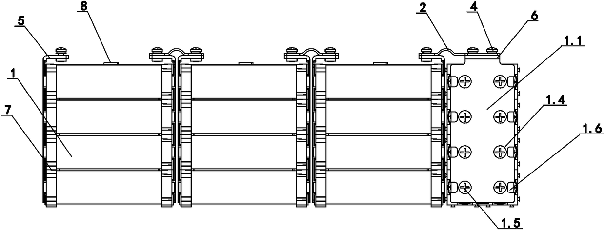
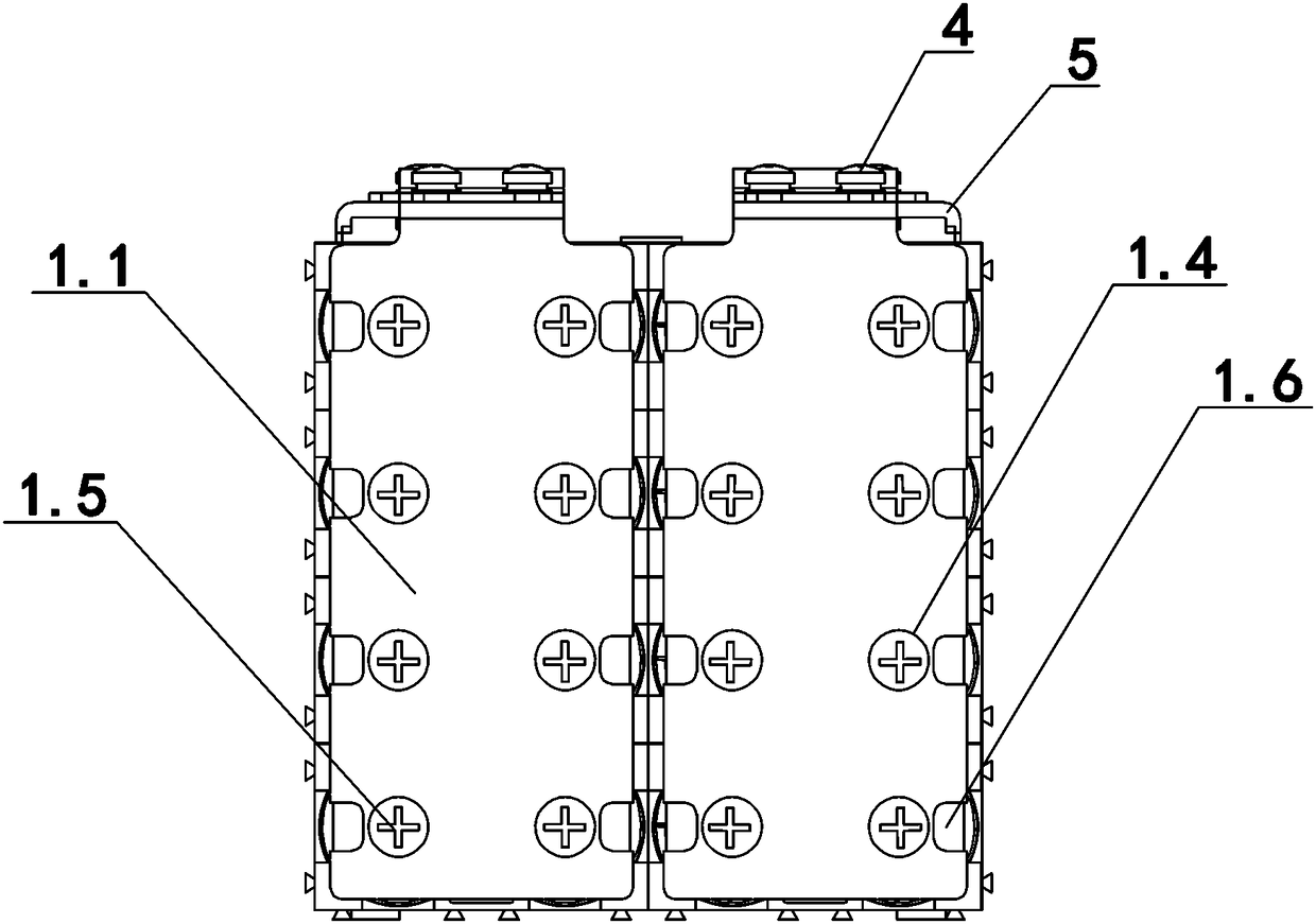
[0029] refer to Figure 1-6 , the present invention provides a technical solution: a package structure suitable for a cylindrical cell battery pack carrying a large current, including a plurality of vertical cylindrical cell battery cells 1, the positive and negative poles of adjacent vertical cylindrical cell battery cells 1 The poles are connected end-to-end through connectors 2, and also include a horizontal cylindrical battery cell 3, which is arranged at the end of the vertical cylindrical battery cell 1 and connected to the ...


PUM


Abstract

The invention discloses a cylindrical cell battery pack packaging structure suitable for bearing a large current. The cylindrical cell battery pack packaging structure suitable for bearing the large current comprises multiple longitudinal cylindrical cell battery monomers (1) of which negative and positive electrodes are connected end to end through connecting components (2), and horizontal cylindrical cell battery monomers (3) which are installed at the end parts of the longitudinal cylindrical cell battery monomers (1) and form U-type arrangement with the longitudinal cylindrical cell battery monomers (1). The cylindrical cell battery monomer comprises a copper current-carrying plate (1.1), a nickel sheet (1.2) and multiple cylindrical cells (1.3). The copper current-carrying plate (1.1)is installed at two negative and positive ends of the cylindrical cells (1.3). The nickel sheet (1.2) is installed between the copper current-carrying plate (1.1) and the cylindrical cells (1.3). Thenickel sheet (1.2) is connected with electrodes of the cylindrical cells (1.3) and the copper current-carrying plate (1.1). The cylindrical cell battery pack packaging structure is capable of bendinglugs at two sides of the nickel sheet to a groove in the front face of the copper current-carrying plate, the structure is simple, and a battery monomer parallelly-connected structure is capable of increasing a thickness of the copper current-carrying plate according to the need, so a design requirement of the oversize current is satisfied.

Description

technical field [0001] The invention relates to the field of battery manufacturing, in particular to a package structure of a cylindrical cell battery group suitable for carrying large current. Background technique [0002] Cylindrical batteries have been widely promoted and used due to their well-known advantages. At present, the most common series-parallel connection method of cylindrical batteries is single energy storage spot welding. The disadvantage of this method is that if the bracket is not used, the heat dissipation of the battery pack is not good. Well, if the bracket is used, the after-sales maintenance and recycling of the single battery is a big problem, and the pure nickel strip is spot-welded. In order to meet the high-current work, it is necessary to spot-weld multiple nickel strips, the production efficiency is low, and the same battery The core needs to withstand multiple spot welding pressures, which affects the performance of the single cell. Moreover, i...

Claims


Application Information

Patent Timeline
Patent Type & Authority Applications(China)
IPC IPC(8): H01M2/26H01M10/04H01M10/615H01M10/6561H01M50/531
CPCH01M10/0422H01M10/615H01M10/6561H01M50/531Y02E60/10Y02P70/50
Inventor 敬良胜夏甫根贾伟倪飞
Owner 四川众联航泰科技有限公司
Why Eureka
Try Eureka