A tension-compression composite plate stretch forming machine

A stretch forming and composite technology, applied in the direction of aircraft parts, feeding devices, manufacturing tools, etc., can solve the problems of expensive equipment, large transition zone allowance, complex hydraulic control system and electrical control system, etc., and achieve hydraulic control Simplified system and electrical control system, uniform distribution of tensile stress and strain, and easy operation and maintenance

Active Publication Date: 2020-05-26
JILIN UNIV
View PDF8 Cites 0 Cited by
  • Summary
  • Abstract
  • Description
  • Claims
  • Application Information

AI Technical Summary

Problems solved by technology

When traditional stretch forming machines form double-curvature skin parts, the distribution of tensile stress and tensile strain in the transverse direction of the sheet is obviously uneven, and defects such as wrinkles and cracks are prone to occur, and a large transition zone allowance is required, and the material utilization rate Extremely low, at the same time, the high precision requirements of the equipment lead to complex control system and expensive equipment
Although the currently used stretch forming machine has improved the uniformity of the tensile stress and strain distribution of the plate during stretch forming to a certain extent, its hydraulic control system and electrical control system are still very complicated, the manufacturing cost is high, and it cannot Eliminate the bending force brought to the sheet by the vertical oil cylinder on the clamping device during stretch forming, so the forming quality of the drawn parts needs to be improved

Method used


Image

  • A tension-compression composite plate stretch forming machine
  • A tension-compression composite plate stretch forming machine
  • A tension-compression composite plate stretch forming machine

Examples


Embodiment Construction

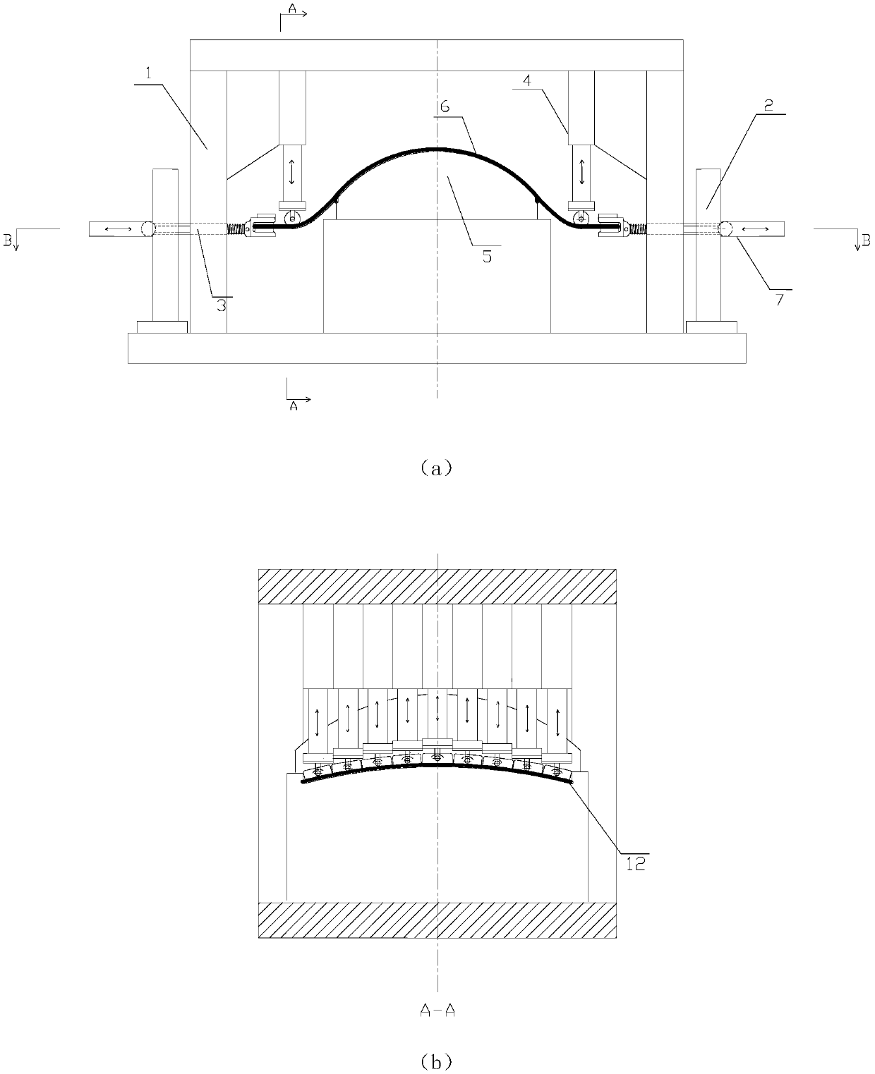
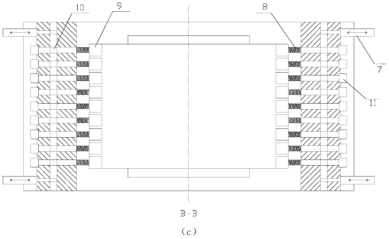
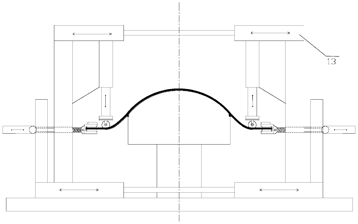
[0022] The specific content and working process of the present invention will be further described below in conjunction with the embodiments shown in the accompanying drawings.

[0023] The pressing device of the tension-compression composite plate stretch forming machine of the present invention is arranged in a row by a plurality of pressing mechanisms, and the pressing mechanisms are composed of rollers, hydraulic cylinders, pins and brackets. During the stretch forming process of the sheet, due to the uneven deformation and double curvature deformation of each part of the sheet, the roller can generate a certain corner around the pin to adapt to the change of the sheet. The clamping mechanism of the stretch forming machine is composed of clamps, hinged rods, return springs and guide rollers. The clamps are composed of hydraulic cylinders, clamping racks, upper and lower clamping blocks and are arranged in a row with the hinged rods. Head swing function. The function of th...


PUM


Abstract

The invention discloses a stretching and pressing combined type plate stretch forming machine which is plastic working equipment for stretch forming of a plate type three-dimensional curved surface piece, and belongs to the field of mechanical engineering. A first object of the invention is to simplify hydraulic pressure of equipment and an electrical control system to lower the manufacturing cost; and a second object is to eliminate bending force on a plate when a vertical oil cylinder on a previous clamping device is loaded, so that pulling stress and strain of the stretch forming piece aredistributed more uniformly, and the shape stability and material utilization of the formed piece are improved. The stretch forming machine mainly consists of a rack, guide devices, downward pressing devices, clamping devices and horizontal prestretching devices (as shown in figures); the rack and the guide devices support the downward pressing devices, the clamping devices and the horizontal prestretching devices on the two sides; each clamping device consists of a plurality of clamping mechanisms; the downward pressing devices consists of a plurality of downward pushing mechanisms; the clamping mechanisms are arranged on the two sides of a mould in a row correspondingly; the downward pushing mechanisms are arranged on the two sides of the mould in a row correspondingly; and the horizontalprestretching devices consist of four hydraulic oil cylinders and universal joints and are arranged on the guide devices on the two sides.

Description

technical field [0001] The invention discloses a tension-compression composite plate stretch forming machine, which is a plastic processing equipment used for forming plate-like three-dimensional curved surface parts, and belongs to the field of mechanical engineering. Background technique [0002] Stretch forming machine is widely used to form double-layered parts in aerospace, high-speed rail, ships and other fields due to its unique advantages-making the inner and outer layers of the sheet generate tensile stress and tensile strain in the stretching direction to reduce the springback of the workpiece. Curvature skinned parts. When traditional stretch forming machines form double-curvature skin parts, the distribution of tensile stress and tensile strain in the transverse direction of the sheet is obviously uneven, and defects such as wrinkles and cracks are prone to occur, and a large transition zone allowance is required, and the material utilization rate At the same ti...

Claims


Application Information

Patent Timeline
Patent Type & Authority Patents(China)
IPC IPC(8): B21D31/00B21D43/00B21D53/88B21D53/92
CPCB21D31/00B21D43/003B21D53/88B21D53/92
Inventor 付文智林琳李明哲刘英男
Owner JILIN UNIV
Why Eureka
Try Eureka