
An Intelligently Adjustable Negative Pressure Fastening Corrective Skull Traction Device
A technology of traction device and skull, which is applied in the field of medical equipment, can solve problems such as cartilage damage, depression, and delayed rehabilitation, and achieve the effect of easy disassembly, fast connection, and favorable recovery
- Summary
- Abstract
- Description
- Claims
- Application Information
AI Technical Summary
Problems solved by technology
Method used
Image

Examples
Embodiment Construction
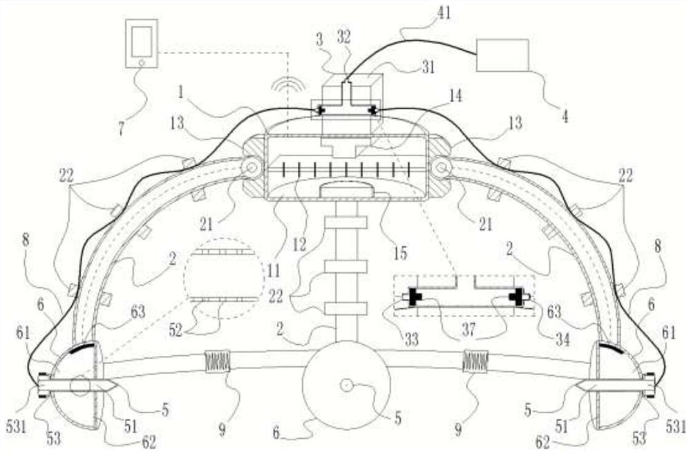
[0031] Attached below Figure 1-5 The present invention will be described in further detail.
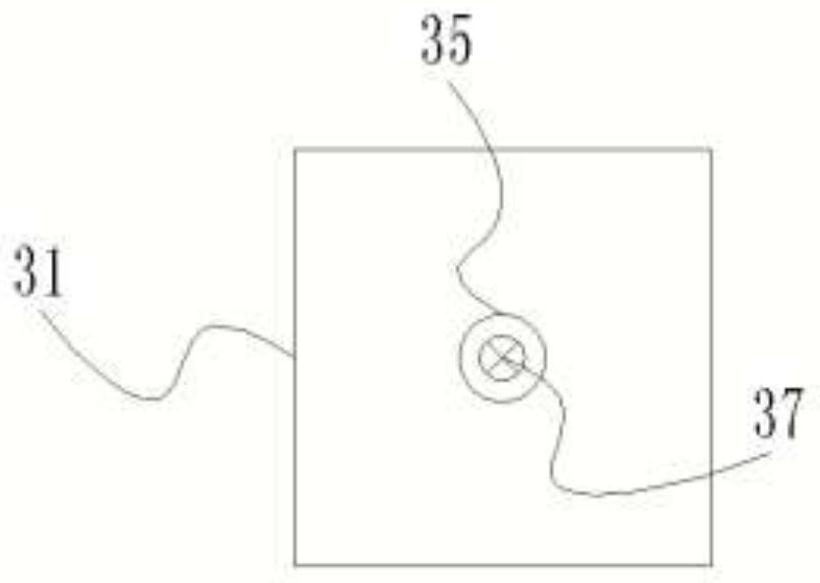
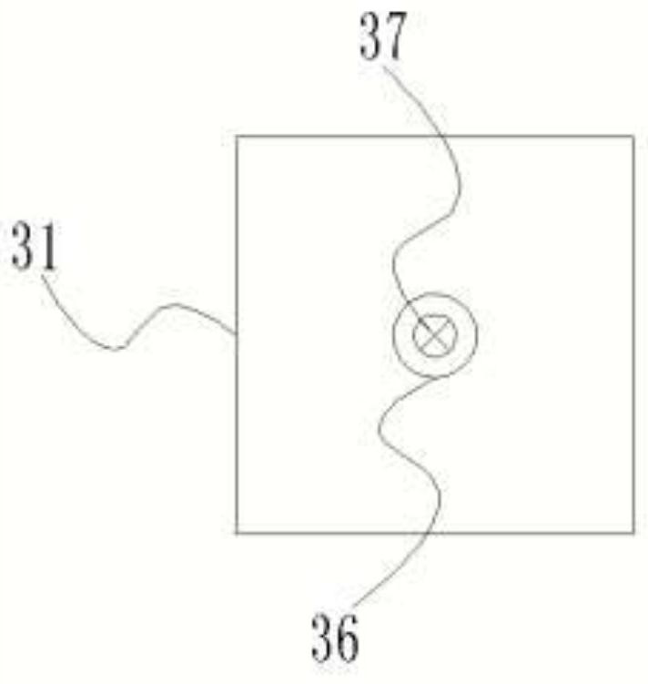
[0032] Such as figure 1As shown, an intelligently adjustable negative pressure fastening corrective skull traction device includes a central connection part 1, a traction bow 2, a connector 3, a negative pressure generator 4, a fixing screw 5, and a fixing pad 6. The central connection Part 1 includes a cylindrical shell 11, an MCU chip 12, a connection interface 13, a built-in wifi module 14, and a battery 15. The MCU chip 12 is fixed laterally at the center of the cylindrical shell 11, and the built-in wifi module 14 is electrically connected to the MCU chip 12. The top is connected with the external monitoring terminal 7 through wireless signals, so that the fixing situation of the traction device can be grasped at any time. The battery 15 is located below the MCU chip 12, and supplies power for the MCU chip 12 and the built-in wifi module 14. There are four connection interfaces...
PUM
 Abstract
Description
Claims
Application Information