Sludge cleaning equipment for sewage treatment

A technology for sewage treatment and cleaning equipment, which is applied in grain treatment, separation methods, sedimentation separation, etc. It can solve the problems of different cleaning difficulties, increased work costs, and idling of sludge pumps, so as to reduce work costs and prevent clogging of sludge The effect of management and cost reduction

Active Publication Date: 2021-02-26
海南诚和源水务工程质量检测有限公司
View PDF8 Cites 0 Cited by
  • Summary
  • Abstract
  • Description
  • Claims
  • Application Information

AI Technical Summary

Problems solved by technology

[0006] The object of the present invention is to provide a kind of sludge cleaning equipment for sewage treatment, to solve the problem that the method of cleaning sludge proposed in the above background technology is single, and the difficulty of cleaning is different when the sludge is at different depths. When the sludge is deep, sludge can be used The pump is directly pumped, with high efficiency and fast speed, which can improve work efficiency and reduce the labor intensity of the staff. However, when the sludge is shallow, if you continue to use the sludge pump, it is likely to cause the motor to burn out due to the idling of the sludge pump. Therefore It is necessary to change the way of cleaning the sludge as the depth of the sludge decreases, and the sewage treatment equipment is relatively large, so it is necessary to move the sludge cleaning equipment to increase the cleaning range of the sludge cleaning equipment, which can avoid the increase caused by the use of larger equipment. The problem of high working cost, and the need to cut the clumps of sludge to prevent the problem of clogging the sludge pipe

Method used


Image

  • Sludge cleaning equipment for sewage treatment
  • Sludge cleaning equipment for sewage treatment
  • Sludge cleaning equipment for sewage treatment

Examples


Embodiment Construction

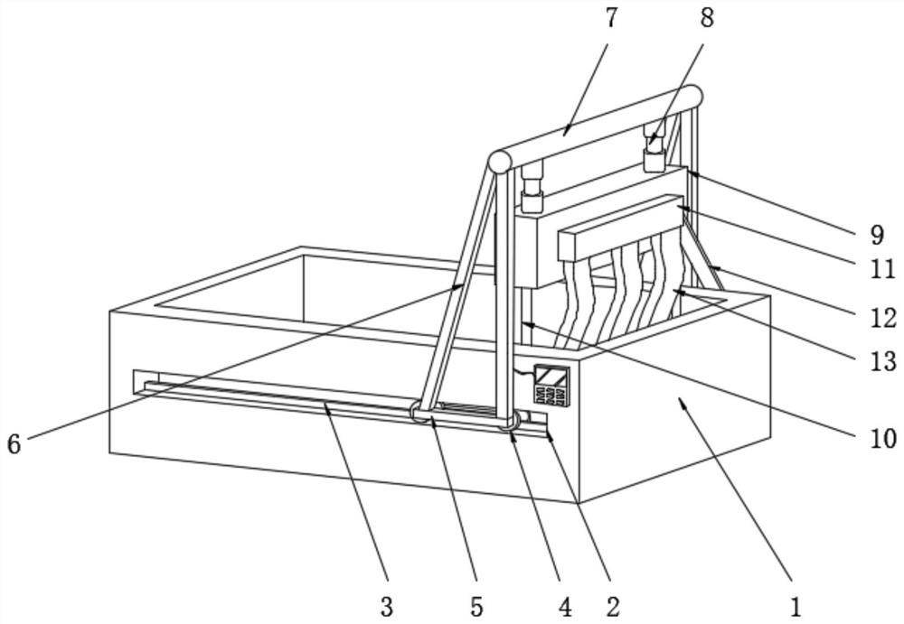
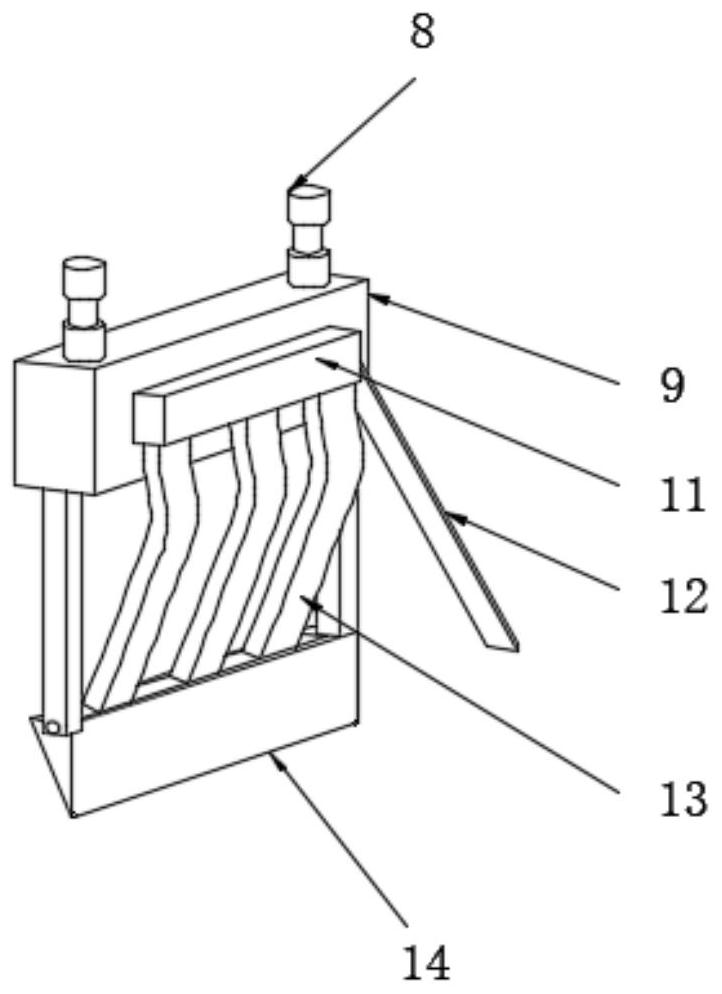
[0028] see Figure 1-2 , in the embodiment of the present invention, a kind of sludge cleaning equipment for sewage treatment comprises a sedimentation tank 1, and both sides of the sedimentation tank 1 are provided with a slide rail groove 2, and the inside of the slide rail groove 2 is fixedly equipped with a partition 3, and the sliding The inside of the rail groove 2 is equipped with pulleys 4 near the two sides of the partition plate 3. The pulley 4 is stuck on the outside of the partition plate 3 to prevent the pulley 4 from falling off from the slide rail groove 2, and the partition plate 3 allows the pulley 4 to move along the fixed The route is forward or backward, and the outer side of the pulley 4 is fixedly installed with a mounting plate 5, and the driving motor of the mounting plate 5 is connected with the pulley 4, which can automatically change the working place of the sludge cleaning equipment. The upper surface of the mounting plate 5 is fixedly mounted with a...


PUM


Abstract

The invention discloses a sludge cleaning device for sewage treatment, which comprises a sedimentation tank. Both sides of the sedimentation tank are provided with slide rail grooves. Pulleys are installed on both sides close to the partition, and a mounting plate is fixedly mounted on the outside of the pulley, a side arm is fixedly mounted on the upper surface of the mounting plate, and a beam is fixedly mounted on the top side of the side arm A hydraulic rod is fixedly installed on the lower surface of the hydraulic rod, and a motor box is fixedly installed at the bottom end of the hydraulic rod, and a support frame is arranged on the lower surface of the motor box. The present invention can clean up the silt produced in sewage treatment, realize automation, improve work efficiency, and drive the pulley to move by driving the motor, so that the dredging range of the silt cleaning equipment can be changed, the labor burden of the staff can be reduced, and the use of large-scale The cost of machinery can reduce the cost of work.

Description

technical field [0001] The invention relates to a sludge cleaning device, in particular to a sludge cleaning device for sewage treatment. Background technique [0002] Sewage treatment is the process of purifying sewage to meet the water quality requirements of a certain water body for drainage or reuse. Sewage treatment is widely used in various fields such as construction, agriculture, transportation, energy, petrochemical, environmental protection, urban landscape, medical treatment, catering, etc., and it is also increasingly entering the daily life of ordinary people. In the treatment of some sewage, sedimentation tanks A large amount of sludge will be deposited. If the sludge cannot be cleaned in time, the water level will be too high. At the same time, it will cause secondary pollution to the water in the sediment, which will reduce the efficiency of sewage treatment. If a sensor is installed, the sludge will cover the surface of the sensor The accuracy of the sensor...

Claims


Application Information

Patent Timeline
Patent Type & Authority Patents(China)
IPC IPC(8): B01D21/02B01D21/24B02C18/02
CPCB01D21/02B01D21/245B02C18/02
Inventor 车国容
Owner 海南诚和源水务工程质量检测有限公司
Why Eureka
Try Eureka