Feeding conveying device of ring bobbin and control method thereof

The technology of a conveying device and a control method is applied in the field of spun yarn bobbin feeding conveying device and its control, which can solve the problems of low efficiency of cleaning residual yarn, high labor intensity of residual yarn cleaning, etc., so as to improve the degree of automation and reliability, improve residual yarn The effect of yarn cleaning efficiency and labor intensity reduction

Active Publication Date: 2019-01-18
HUBEI TIANMEN TEXTILE MACHINERY
View PDF8 Cites 8 Cited by
  • Summary
  • Abstract
  • Description
  • Claims
  • Application Information

AI Technical Summary

Problems solved by technology

[0003] The purpose of the present invention is to overcome the defects and problems of high labor intensity and low efficiency of residual yarn cleaning in the prio

Method used


Image

  • Feeding conveying device of ring bobbin and control method thereof
  • Feeding conveying device of ring bobbin and control method thereof
  • Feeding conveying device of ring bobbin and control method thereof

Examples


Embodiment 1

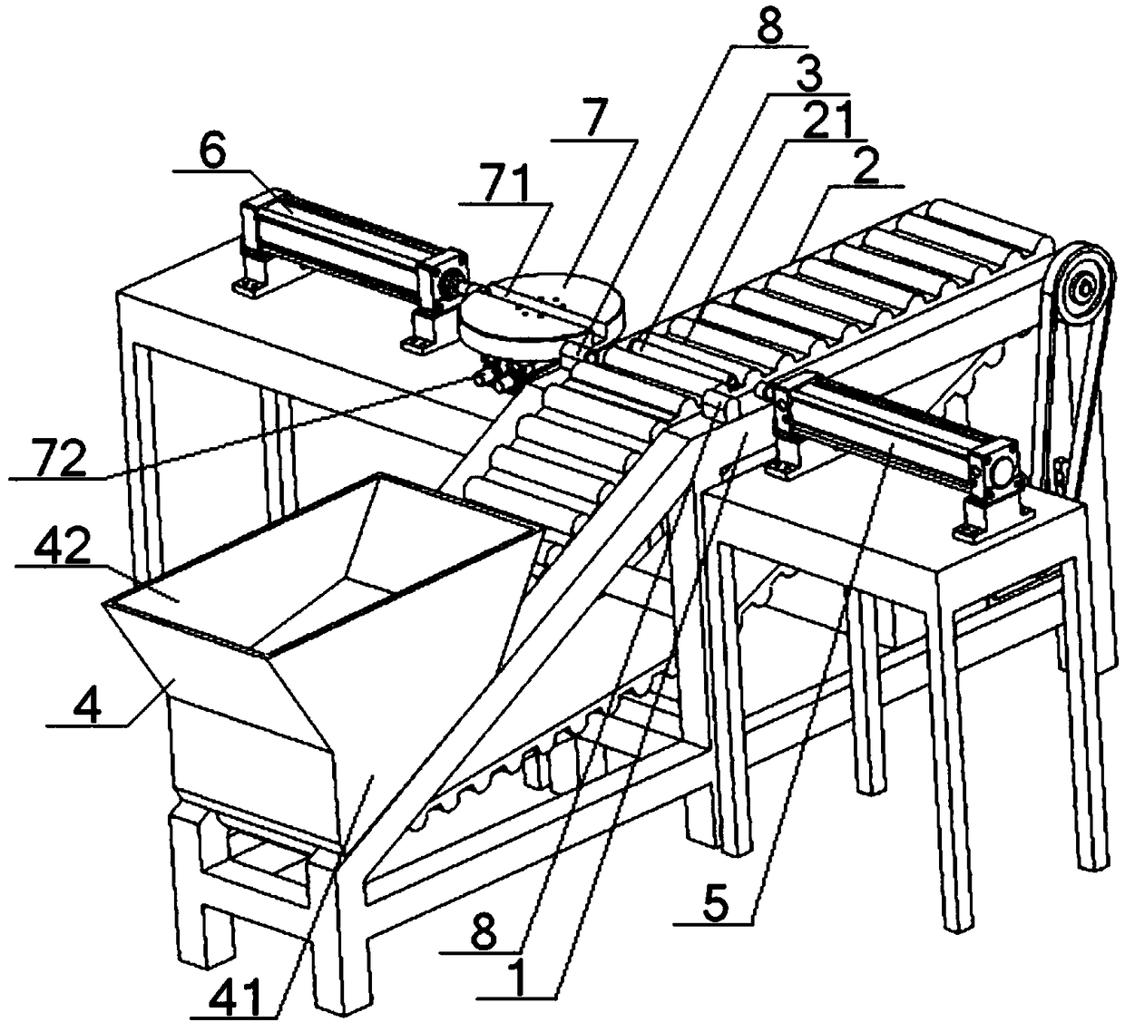
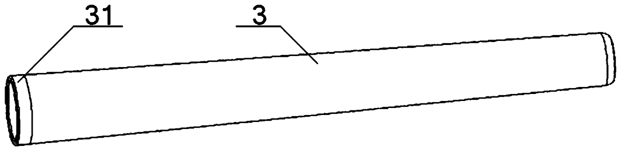
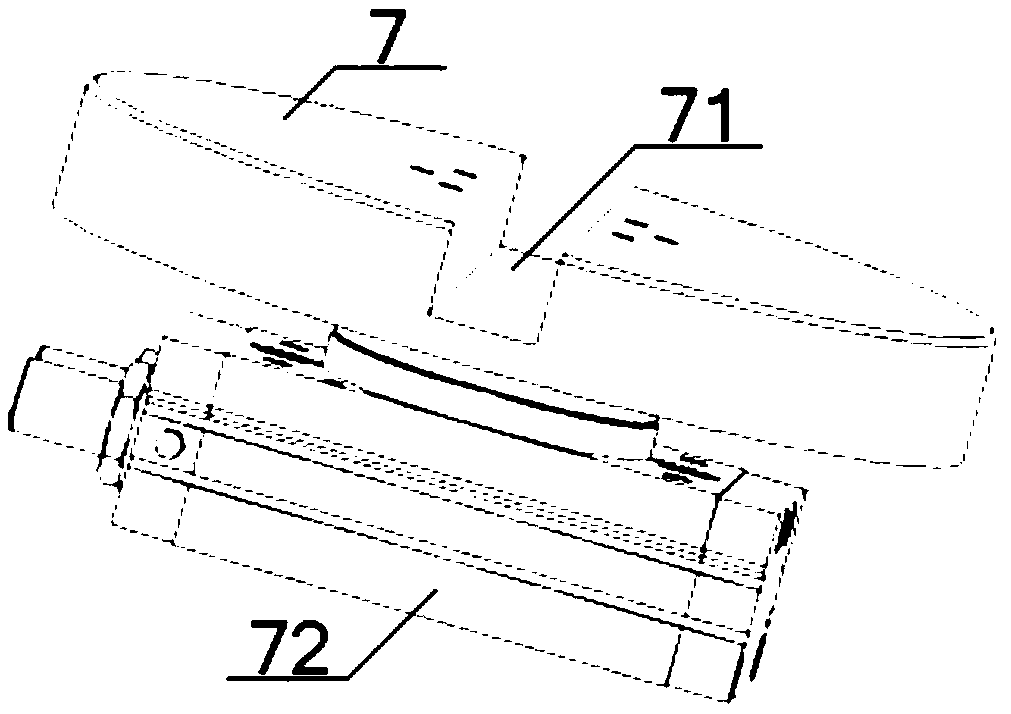
[0054] see Figure 1 to Figure 3 , a spinning tube feeding and conveying device, comprising a support 1 and a conveyor belt 2 arranged on it, a plurality of storage compartments 21 are uniformly arranged on the outer peripheral surface of the conveyor belt 2, and a spinning tube 3 is arranged in the storage compartment 21, The spun bobbin 3 has a circular platform structure, and a hopper 4 is provided on the support 1 above the conveyer belt 2, and a No. 1 air cylinder 5 is arranged on one side of the conveyer belt 2, and the output end of the No. 1 air cylinder 5 is aligned with the spun bobbin 3. The other side of the conveyor belt 2 is provided with a No. 2 cylinder 6, and a rotary disc 7 is provided between the No. 2 cylinder 6 and the conveyor belt 2. The top of the rotary disc 7 is provided with a groove 71 along its diameter direction. The two open ends of the groove 71 are respectively aligned with the output end of the No. 2 cylinder 6 and the spinning bobbin 3, and a...

Embodiment 2

[0057] Basic content is the same as embodiment 1, the difference is:

[0058] see figure 1 , figure 2 , the large-diameter end of the spun bobbin 3 is covered with a metal ring 31 , and metal sensors 8 are arranged on the positions on both sides of the storage compartment 21 on the support 1 .

Embodiment 3

[0060] Basic content is the same as embodiment 1, the difference is:

[0061] see figure 1 , Figure 4 , Figure 5 , the support 1 is a right-angle trapezoidal structure, the upper bottom of the support 1 and the right-angle waist are provided with a No. 1 belt pulley 9, the lower bottom of the support 1 and the inclined waist are provided with a No. 2 pulley 10, and the upper bottom of the support 1 A No. 3 pulley 11 is arranged at the position connecting with the oblique waist, and a belt tensioner 12 is arranged below the No. 3 pulley 11. One end of the inner side of the conveyor belt 2 is installed on the No. 1 pulley 9, and the other end of the inner side of the conveyor belt 2 is installed. On the No. 2 pulley 10, the middle part of the inside of the conveyor belt 2 is installed on the No. 3 pulley 11 and the belt tensioner 12 respectively, and the No. 1 pulley 9 is connected with the transmission motor 14 through the power belt 13; the hopper 4 includes The No. 1 pla...


PUM


Abstract

The invention discloses a feeding conveying device of ring bobbin. The device comprises a bracket and a conveying belt arranged on the bracket, a plurality of storage cases are uniformly arranged on the periphery surface of the conveying belt, and the ring bobbin is arranged in one of the storage cases and is of a circular truncated cone structure; a hopper is arranged on the portion, located above the conveying belt, of the bracket, a first air cylinder is arranged on one side of the conveying belt, and the output end of the first air cylinder is aligned with the ring bobbin; a second air cylinder is arranged on the other side of the conveying belt, a revolving turntable is arranged between the second air cylinder and the conveying belt, and a groove is formed in the top of the revolvingturntable in the diameter direction of the revolving turntable; two opening ends of the groove are respectively aligned with the output end of the second air cylinder and the ring bobbin, and a revolving air cylinder is arranged at the bottom of the revolving turntable; a metal ring sleeves the large diameter end of the ring bobbin, and metal sensors are arranged on the portions, located on the two sides of each storage case, of the bracket. The design of the device not only reduces the labor intensity of residual yarn cleaning but also improves the efficiency of cleaning residual yarns away.

Description

technical field [0001] The invention relates to the field of textile technology, in particular to a spun bobbin feeding and conveying device and a control method thereof, which are mainly suitable for reducing the labor intensity of residual yarn cleaning and improving the efficiency of residual yarn cleaning. Background technique [0002] The yarn is wound on the surface of the bobbin for the weaving and production process of spinning. Generally, when there is a small amount of yarn residue on the surface of the bobbin, the worker will replace the bobbin. In order to ensure the repeated use of the spun bobbin, it is necessary to manually remove the remaining yarn on the surface. Due to the huge amount of spun bobbin used in the spinning and production process, the labor intensity for workers to remove the residual yarn on the surface of the spun bobbin is high, and it takes time to remove the residual yarn. Cutting with blades is mostly used, which easily scratches the sur...

Claims


Application Information

Patent Timeline
IPC IPC(8): B65G47/04B65G47/24B65G23/44B65G47/82
CPCB65G23/44B65G47/04B65G47/24B65G47/82B65G2201/0214
Inventor 张成俊李冬冬左小艳游良风刘念张弛朱里叶祥虎陈卓
Owner HUBEI TIANMEN TEXTILE MACHINERY
Why Eureka
Try Eureka