Method and device for controlling edge waves of strip steel joints
A control method and strip technology, applied in the field of strip rolling, can solve problems such as lag in edge wave control, avoid lag, improve shape control effect, and solve the effect of edge wave control lag
- Summary
- Abstract
- Description
- Claims
- Application Information
AI Technical Summary
Problems solved by technology
Method used
Image
Examples
no. 1 example
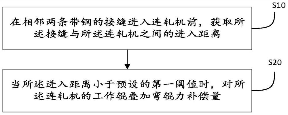
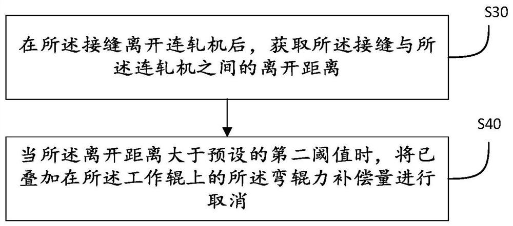
[0037] see figure 1 , is a flowchart of a strip seam control method provided by a preferred embodiment of the present invention. The following will be figure 1 The specific process shown will be described in detail.
[0038] Step S10: Before the joint of two adjacent steel strips enters the continuous rolling mill, obtain the entering distance between the joint and the continuous rolling mill.
[0039] In step S10, a weld detector can be set in front of the continuous rolling mill, and the entry distance between the seam and the continuous rolling mill can be defined as the first working distance between the weld detector (for detecting the seam) and the continuous rolling mill. distance between the rollers. For example, a weld detector can be placed 5 meters before the first work roll of the tandem mill. The entry distance is the distance between the strip and the continuous rolling mill when it moves in the direction of entering the continuous rolling mill.
[0040] It ...
no. 2 example
[0054] In this embodiment, different from the first embodiment, in order to improve the effect of edge wave elimination in the process of seam rolling and ensure the rolling efficiency, a strip joint provided in this embodiment The seam wave control method will also adjust the speed of the strip according to the shape of the strip, and the specific steps are as follows:
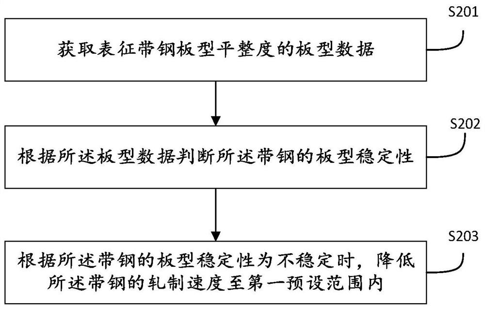
[0055] Please refer to image 3 , before step S20, before the step of superimposing the roll bending force compensation amount on the work rolls of the continuous rolling mill, it also includes:
[0056] Step S201: Obtain the shape data representing the flatness of the strip steel plate.
[0057] In this step S201, the shape data representing the flatness of the strip steel plate can be directly obtained by measuring the shape meter, such as the IU value read by the shape meter (a value or a bar graph used to measure the shape condition).
[0058] Step S202: Judging the shape stability of the steel strip ac...
no. 3 example
[0067] see Figure 5 In this embodiment, a strip seam edge wave control device 300 is provided, which can be used to implement the methods described in the first embodiment and the second embodiment, including: a distance detection module 301, a first roll bending force The superimposing module 302 and the second bending force superimposing module 303 .
[0068] The distance detection module 301 is configured to obtain the entering distance between the joint of two adjacent steel strips and the continuous rolling mill before the joint enters the continuous rolling mill.
[0069] The first roll bending force superposition module 302 is configured to superimpose the roll bending force compensation amount on the working rolls of the continuous rolling mill when the entry distance is less than a preset first threshold.
[0070] The second roll bending force superposition module 303 is configured to superimpose the roll bending force compensation amount on the intermediate roll of...
PUM
 Abstract
Description
Claims
Application Information
 - R&D
- Intellectual Property
- Life Sciences
- Materials
- Tech Scout
- Unparalleled Data Quality
- Higher Quality Content
- 60% Fewer Hallucinations
Browse by: Latest US Patents, China's latest patents, Technical Efficacy Thesaurus, Application Domain, Technology Topic, Popular Technical Reports.
© 2025 PatSnap. All rights reserved.Legal|Privacy policy|Modern Slavery Act Transparency Statement|Sitemap|About US| Contact US: help@patsnap.com


