Flexible casing treatment centrifugal compressor

A centrifugal compressor and casing processing technology, which is applied to machines/engines, mechanical equipment, liquid fuel engines, etc., can solve problems such as limiting the stability expansion capability, affecting the maximum efficiency of the compressor, and achieving the effect of preventing the reduction of efficiency.

Inactive Publication Date: 2019-02-19
汪陈芳
View PDF5 Cites 3 Cited by
  • Summary
  • Abstract
  • Description
  • Claims
  • Application Information

AI Technical Summary

Problems solved by technology

However, the traditional casing slot is a rigid structure, and the slot width does not change with the working conditions of the centrifugal compressor, which limits its expansion stability and affects the maximum efficiency of the compressor

Method used


Image

  • Flexible casing treatment centrifugal compressor
  • Flexible casing treatment centrifugal compressor
  • Flexible casing treatment centrifugal compressor

Examples


Embodiment 1

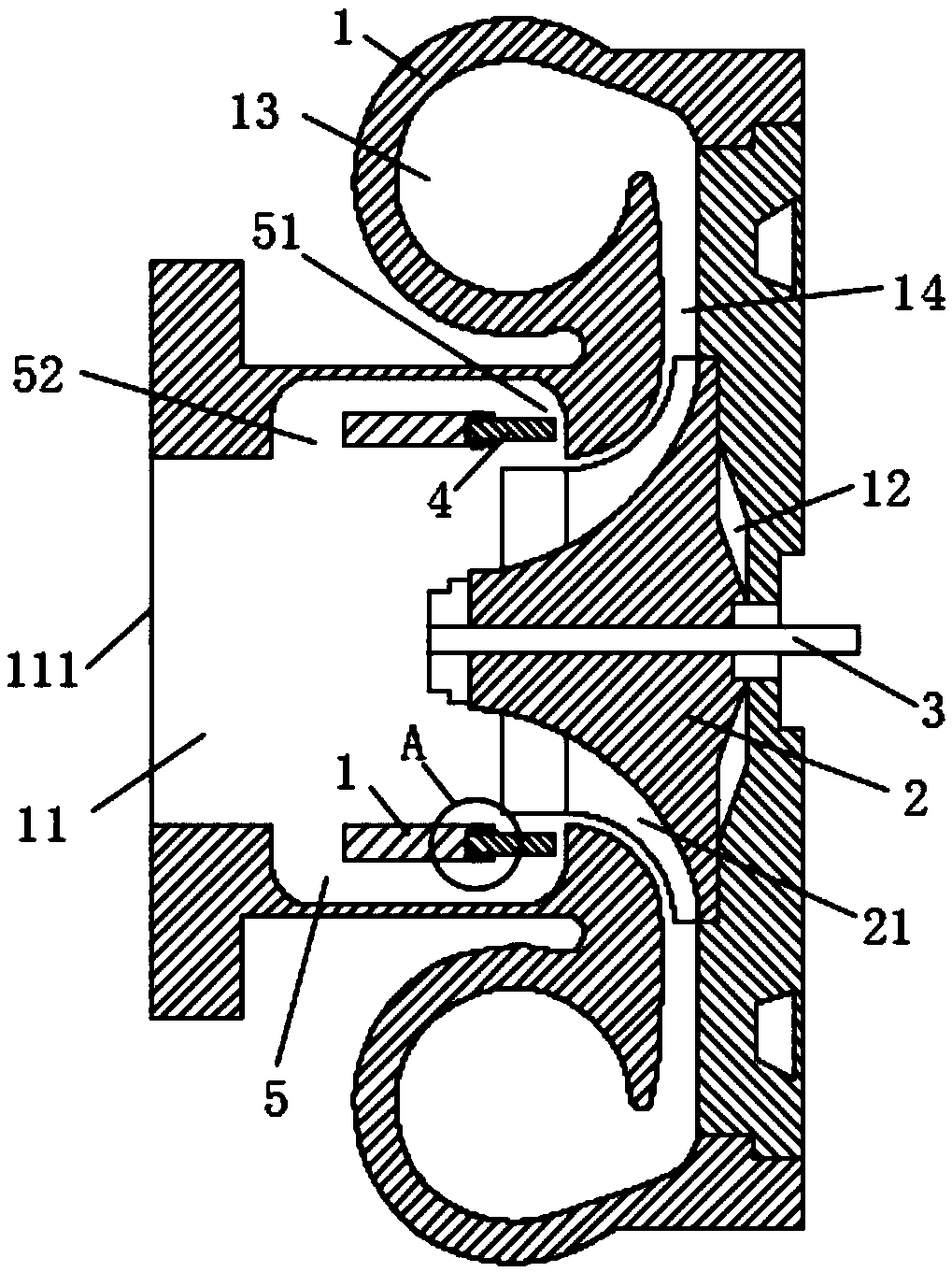
[0021] refer to figure 1 and figure 2 As shown, the present invention provides a flexible case processing centrifugal compressor, including a volute 1 and an impeller 2, characterized in that: a rotating shaft 3 is fixedly inserted in the middle of the impeller 2, and the impeller 2 is fixedly installed on the surface inside the volute 1 There are multiple groups of blades 21, the inner middle of the volute 1 is provided with an air inlet channel 11 horizontally, the volute 1 is provided with an impeller installation cavity 12 at the impeller 2, and the inner two sides of the volute 1 are provided with an air outlet channel 13, the impeller 2 Installed in the impeller installation chamber 12, the front side surface of the volute 1 is provided with an air inlet 111 in the air inlet passage 11, and the inner two sides of the volute 1 are provided with an air outlet 14 at the outlet passage 13, and the impeller installation chamber 12 is respectively It communicates with the ai...

Embodiment 2

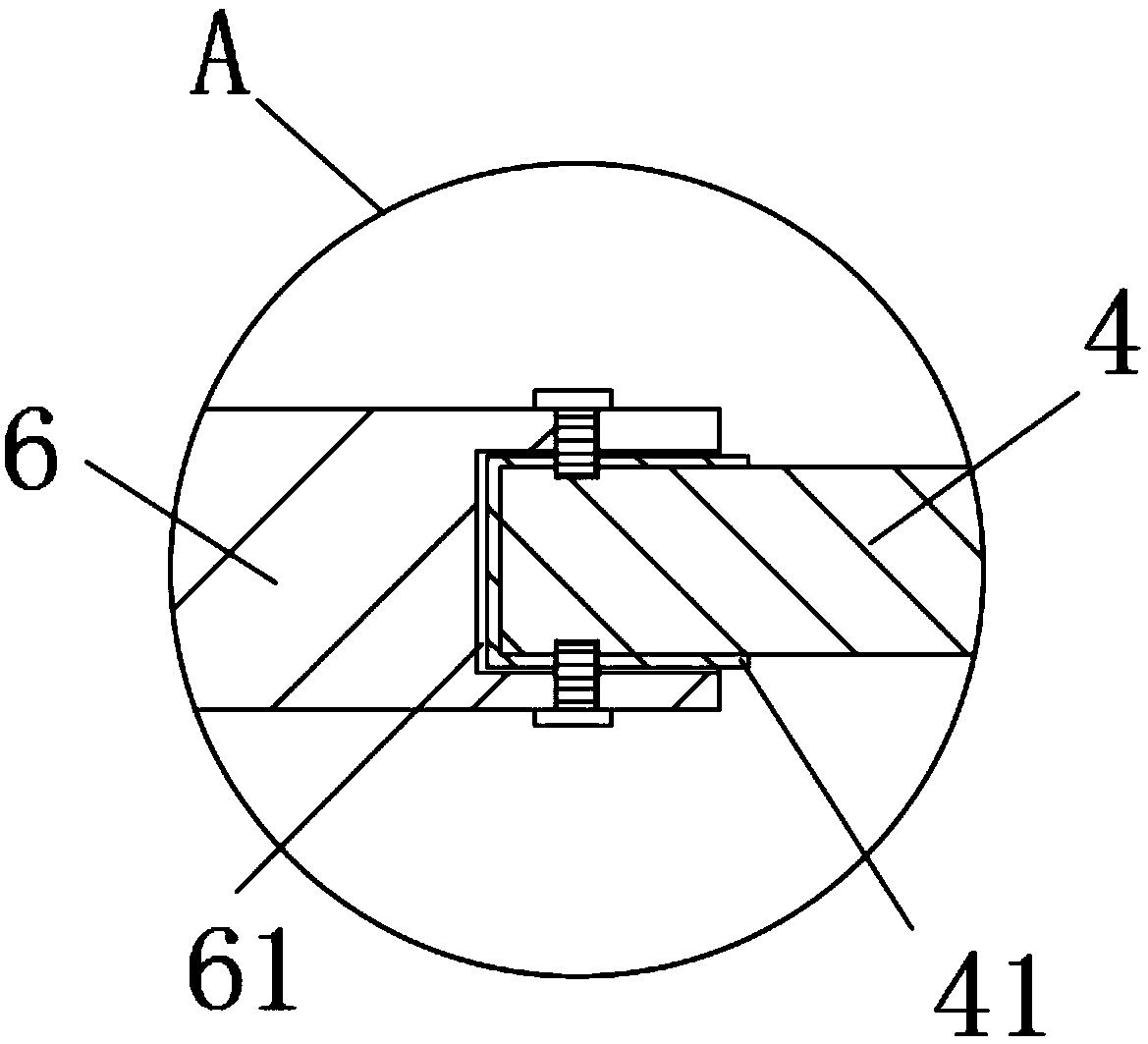
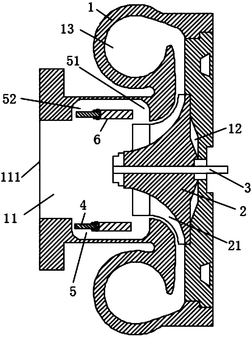
[0023] refer to image 3 The difference between this embodiment and Embodiment 1 is that the splint 41 is fixedly engaged on the end surface of the flexible baffle 4 close to the partition 6, and the surface of the partition 6 near the air inlet 111 is provided with a mounting groove 61 , the flexible baffle 4 is inserted into the installation groove 61 through the splint 41, the outer surface of the partition 6 is provided with screws at the installation groove 61, and the partition 6 fixes the flexible baffle 4 and the splint 41 in the installation groove 61 through the screws , the nut end of the screw is fixedly welded on the outer surface of the partition plate 6 .

Embodiment 3

[0025] refer to image 3 The difference between this embodiment and Embodiment 1 is that: the end surface of the flexible baffle 4 close to the partition 6 is fixedly engaged with a splint 41, and the partition 6 corresponds to the middle part of the bottom surface of the casing groove 5. There is an installation groove 61, and the flexible baffle 4 is inserted into the installation groove 61 through the splint 41. The outer surface of the partition 6 is provided with screws at the installation groove 61, and the partition 6 fixes the flexible baffle 4 and the splint 41 on the In the mounting groove 61 , the nut end of the screw is fixedly welded on the outer surface of the partition plate 6 .

[0026] Working principle: Under normal circumstances, the pressure near the channel of the impeller 2 is not much different from the ambient pressure. The bending degree of the flexible baffle 4 is small, and the gas is not easy to flow out of the casing groove 5, which reduces the flo...


PUM


Abstract

The invention discloses a flexible casing treatment centrifugal compressor. The flexible casing treatment centrifugal compressor comprises a volute and an impeller, air outlet channels are formed in the two side ends in the volute, an air inlet is formed in the position, on an air inlet channel, of the front side surface of the volute, air outlets are formed in the positions, on the air outlet channels, of the two side ends in the volute, an impeller mounting cavity communicates with the air inlet channel and the air outlet channels, casing grooves are formed in the two side walls of the air inlet channel, partition boards are transversely and fixedly arranged in the casing grooves, flexible baffles are arranged on the side surfaces of the partition boards, and gaps are formed between theouter side ends of the flexible baffles and the bottom surfaces of the casing grooves. The compressor carries out operation on the basis of not changing an original centrifugal compressor volute casing treatment mechanism, the compressor is simple and convenient, flowing losses are avoided to a certain degree while the stable work range of the centrifugal compressor is further widened, and the reduction of the efficiency of the centrifugal compressor is effectively prevented.

Description

technical field [0001] The invention relates to the technical field of the centrifuge industry, and more specifically relates to a centrifugal compressor handled by a flexible casing. Background technique [0002] Wheel compressors include two basic types: axial flow and centrifugal. Axial-flow compressors have low single-stage sub-ratio and strong flow capacity, and are suitable for large-scale multi-stage compression systems. Compared with the axial flow compressor, the centrifugal compressor has the characteristics of high single-stage pressure ratio, simple structure, small size, light weight, etc., and can maintain high efficiency in a wide operating range, so it is widely used in Vehicles, ships, some industries and aviation and other fields. [0003] Centrifugal compressor is one of the key components of internal combustion engine turbocharger. In recent years, the technical requirements for energy saving and CO2 emission reduction of internal combustion engines, h...

Claims


Application Information

Patent Timeline
Patent Type & Authority Applications(China)
IPC IPC(8): F04D17/10F04D27/02F04D29/42
CPCF04D17/10F04D27/0215F04D29/4206
Inventor 汪陈芳
Owner 汪陈芳
Why Eureka
Try Eureka