a pile extractor
A technology of pile extractor and pile body, which is applied in the direction of sheet pile wall, building, foundation structure engineering, etc. It can solve the problems that affect the pile pulling effect, it is difficult to give hydraulic cylinder support force, and the base is easy to sink into the soil layer, etc.
- Summary
- Abstract
- Description
- Claims
- Application Information
AI Technical Summary
Problems solved by technology
Method used
Image

Examples
Embodiment 1
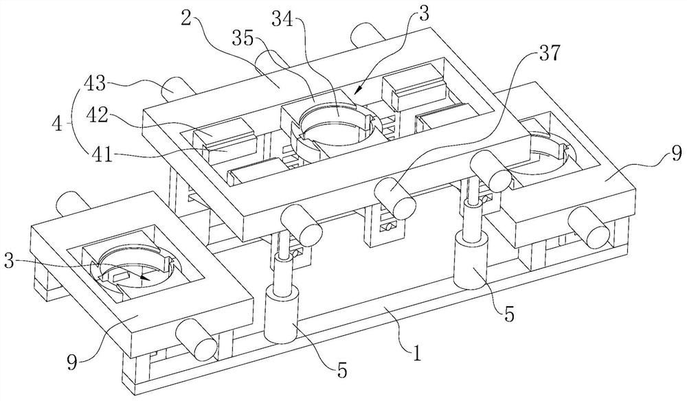
[0037] Embodiment 1: refer to Figure 1-3 , is a pile extractor disclosed in the present invention, comprising a base 1 and a support frame 2, the support frame 2 is installed on the base 1 through a hydraulic cylinder 5 and moves up and down along the height direction of the base 1; the support frame 2 moves along the length direction of the base 1 The two sides of the two sides are symmetrically provided with a fixed frame 9 respectively, and the fixed frame 9 is welded on the base 1; Three groups of piles are adjacent to each other in the clamping soil layer; when the three clamping parts 13 are clamped and fixed with the corresponding pile bodies, the hydraulic cylinder 15 drives the support frame 2 to move upwards, driving the middle pile body out of the soil layer 6-8 meters; then move the base 1, drive the clamping part 1 on one side to clamp the pile body pulled out from the soil layer, and use the reaction force of the pulled out pile body and the pile body on the oth...
Embodiment 2
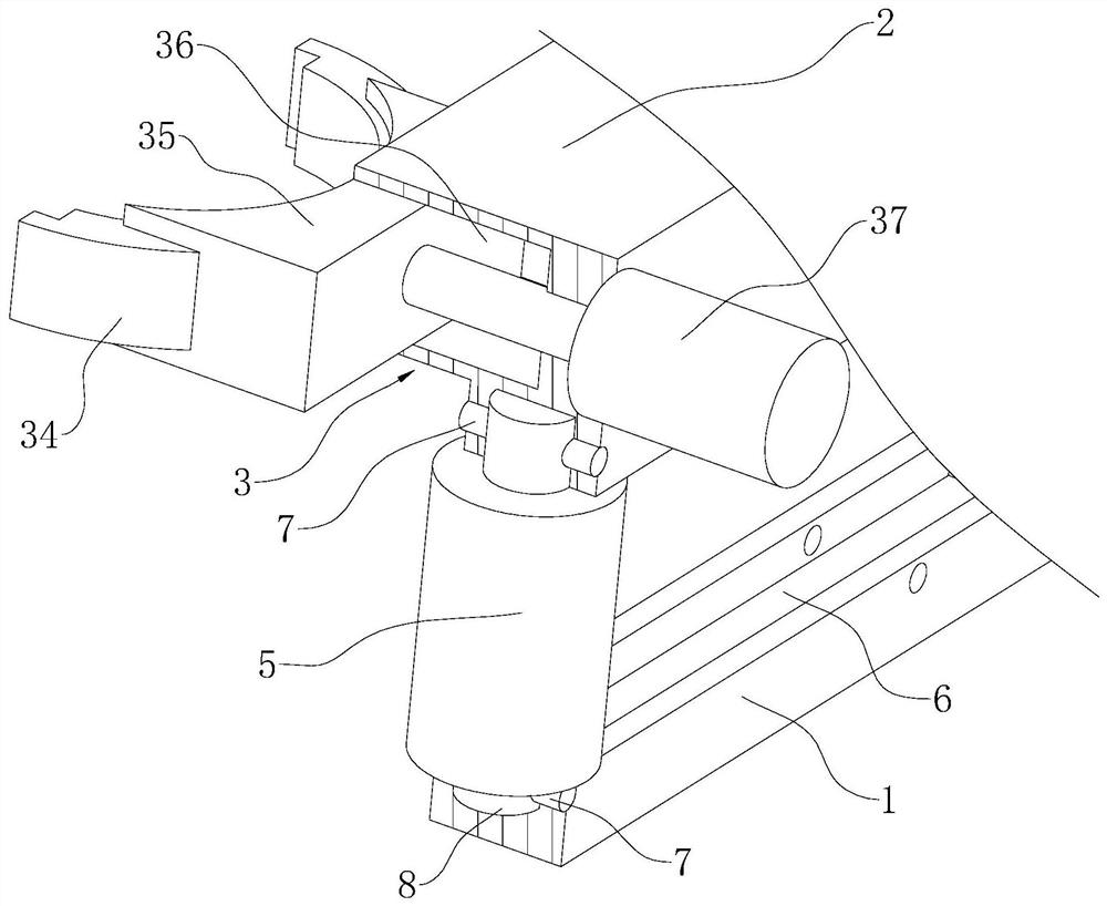
[0041] Embodiment 2: The difference from Embodiment 1 is that, with reference to figure 1 with 3 , the above-mentioned hydraulic cylinder one 5 is provided with two, two hydraulic cylinder one 5 are respectively arranged on both sides of the width direction of the base 1, the lower end of the hydraulic cylinder one 5 is fixed with a roller shaft 8, and the support frame 2 and the base 1 are respectively arranged along the length direction of the base 1. There is provided a chute 6 for insertion of the telescopic shaft and the roller shaft 8 and linear movement, and the movement of the hydraulic cylinder one 5 is restricted by a limiting member.
[0042] The above-mentioned limiting parts include the limiting groove 1 provided on the base 1 and the support frame 2 respectively corresponding to the axes of the hydraulic cylinder 2 37 and the hydraulic cylinder 3 43, the telescopic shaft of the hydraulic cylinder 1 5 and the limiting groove 2 provided on the roller shaft 8, When...
Embodiment 3
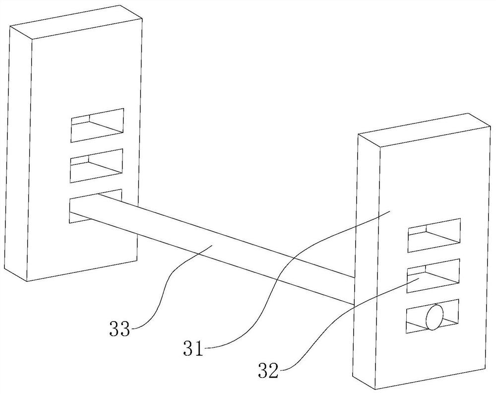
[0044] Embodiment 3: The difference with Embodiment 1 is that, with reference to image 3 with 4 , the support block 1 35, clamping block 1 34, support groove 1 36 and hydraulic cylinder 2 37 in the above clamping member 1 3 are evenly arranged in six groups along the center of the pile body, and the six groups of clamping block 1 34 surround a circle ; Among them, two groups of clamping blocks 134 arranged symmetrically along the width direction of the base are flat on the side facing the pile body, and the other four groups of clamping blocks 134 are curved on the side facing the pile body.
[0045] refer to Figure 5 , in this embodiment, one end of the above-mentioned clamping block 34 in the supporting groove 36 is set on an inclined surface whose upper side is narrower than the lower side, and the inner wall of the supporting block 35 abuts against the inclined surface of the clamping block 34, giving clamping Hold block one 34 facing forward with lower stress.
PUM
 Abstract
Description
Claims
Application Information