Shielded connector and connection method

A connector and shielding technology, applied in the direction of connection, two-part connection device, and components of the connection device, etc., can solve problems such as heightening, impedance mismatch, etc., and achieve improved shielding characteristics, easy impedance matching, and simple structure. Effect

Active Publication Date: 2019-03-26
SMK CO LTD
View PDF7 Cites 0 Cited by
  • Summary
  • Abstract
  • Description
  • Claims
  • Application Information

AI Technical Summary

Problems solved by technology

[0010] However, the greater the number of shielded single-core wires 20 in the shielded electric wire 10, the connection between the many shielded single-core wires 20 exposed by removing the sheath portion 18 and the shielding foil 21 and the male terminal 12, and the shielded connector. Considering the ease of assembly of 11, the more limited the length of the exposed part is, the more likely it is that the impedance mismatch will be caused.

Method used


Image

  • Shielded connector and connection method
  • Shielded connector and connection method
  • Shielded connector and connection method

Examples


Embodiment 1

[0047] Hereinafter, Embodiment 1 of the present invention will be described based on the drawings.

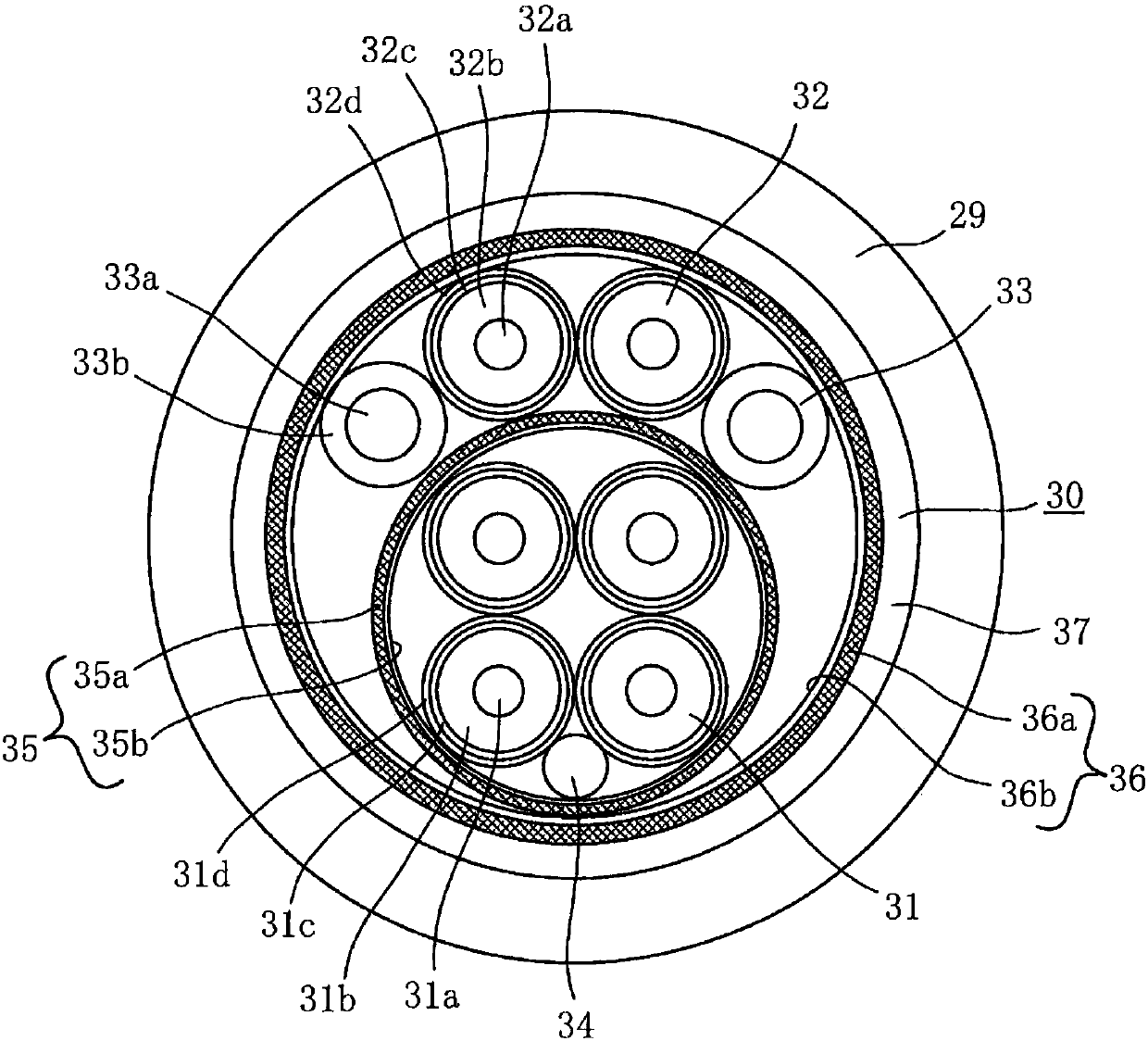
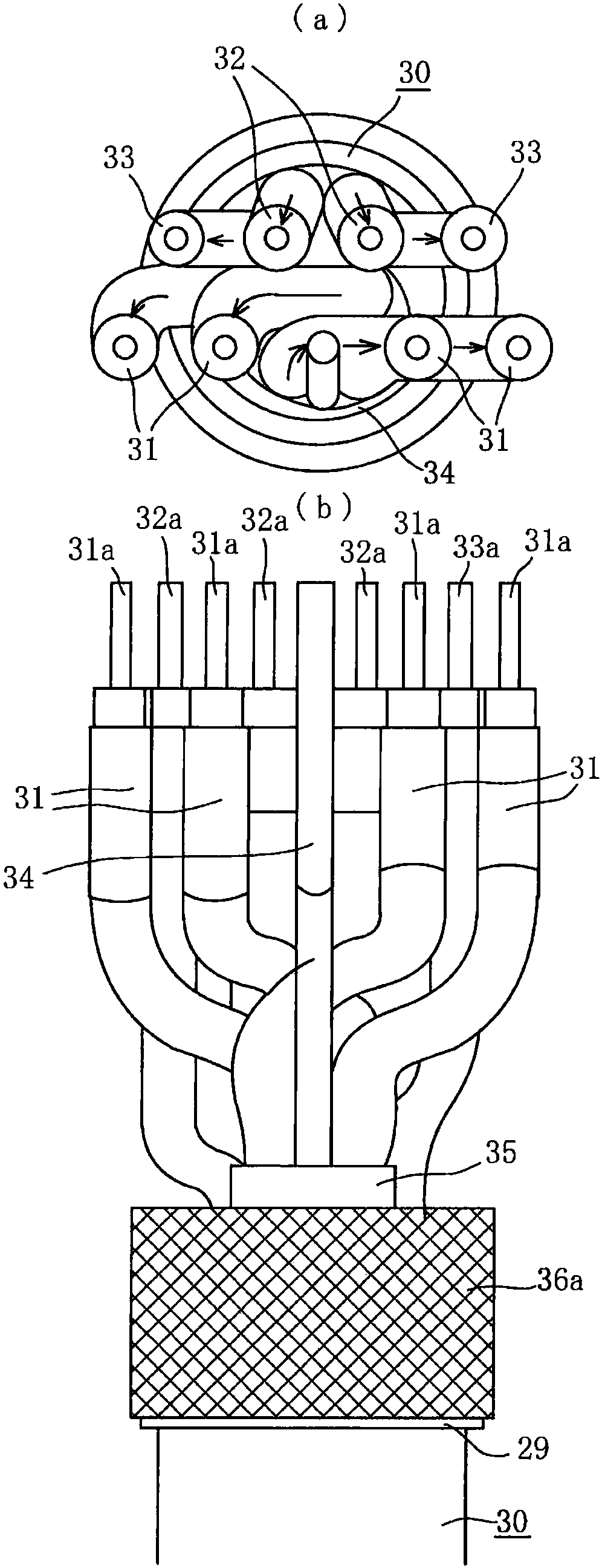
[0048] figure 2 An 8-core composite shielded electric wire 30 used in the shielded connector of the present invention and its connection method is shown. The composite shielded electric wire 30 in this example has six shielded single-core wires, among which four shielded single-core wires 31 are high-speed wires used in differential signal transmission and the like, and two shielded single-core wires 32 include medium-speed wires. This composite shielded electric wire 30 also includes two power supply wires 33 and one drain wire 34 .

[0049] The central conductor 31a of the four high-speed wires 31 is covered by an insulator 31b, and the outer periphery is covered by a single-core wire shield including a horizontally wound shield 31c and an aluminum strip 31d. Similarly, the two medium-speed wires 32 The central conductor 32a is covered with an insulator 32b, and the outer ...

Embodiment 2

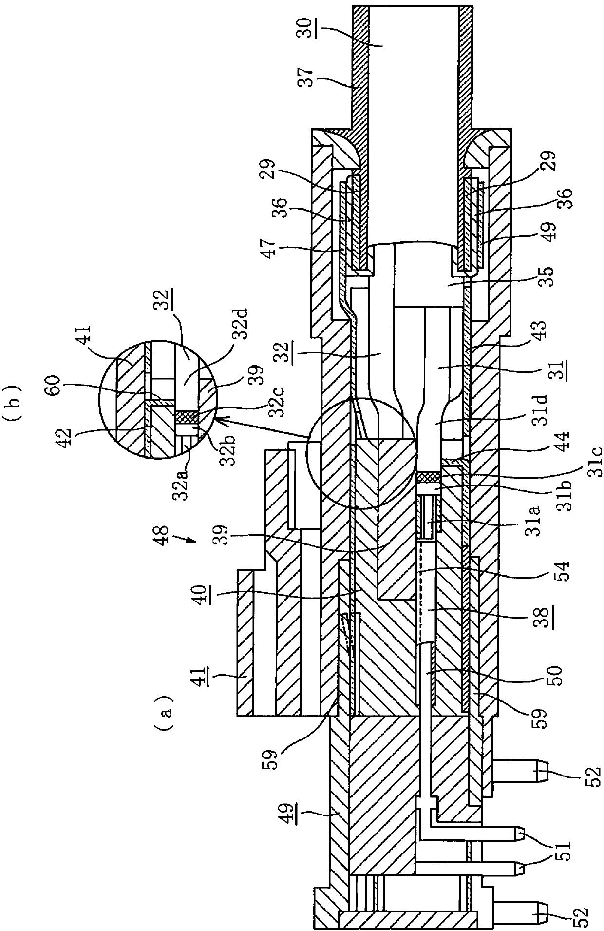
[0066] In the above-described embodiment, the high-speed wire 31 for differential signal transmission is provided with the slit 44 to achieve impedance matching over the entire area of ​​the exposed portion, but the same configuration may be adopted for the medium-speed wire 32 . Thus, if figure 1As shown in (b), a part of the shielding shell 42 is grooved downward to form a cut-and-raised piece 60 of the shielding member of the connector, and the cut-and-raised piece 60 is pressed on the medium-speed wire 32 including the horizontally wound shielding portion 32c and The single-core wire shielding portion of the aluminum tape 32d thereby achieves impedance matching over the entire area of ​​the exposed portion of the medium-speed wire 32 and enhances the shielding effect.

[0067] In said embodiment, for the connection of the single-core wire shielding portion of the high-speed wire 31 and the cut-and-raised piece 44 and / or the connection of the single-core wire shielded port...


PUM


Abstract

The present invention suppresses, as much as possible, the impedance mismatch that causes the connection operation of a shielded single core wire and a connection terminal with a shielding portion ofa removal end portion. A shield connector is formed such that an electrical wire shield portion at an end of an electrical shield wire (30) is removed to expose a plurality of single shield wires (31and/or 32); connection terminals (38) are each connected to the conductor at an end of each exposed single shield wire (31 and/or 32); the connection terminals (38) are held in an inner housing (39);the inner housing (39) and the single shield wires (31 and/or 32) are sheathed with a shield shell (42); and an attachment piece (47) integrated with the shield shell (42) is fixedly attached to an end of the electrical shield wire (31 and/or 32). The shield shell (42) is provided with a connector shield member, and the connector shield member is electrically connected to single wire shield portions of the exposed single shield wires (31 and/or 32).

Description

technical field [0001] The present invention relates to a shielded connector and a connection method thereof. The shielded connector is a shielded connector for connecting a composite cable having a plurality of shielded single-core wires to one shielded wire, and the shielded portion of the exposed shielded single-core wire does not It becomes an open circuit ground, and impedance matching can be achieved in substantially the entire area of ​​the connection processing part. Background technique [0002] Such as Figure 6 As shown, there is known a shielded connector in which a composite cable having a plurality of shielded single core wires is connected to the shielded connector (Patent Document 1). [0003] Should Figure 6 In the connection part of the shielded electric wire 10 and the shielded connector 11, the sheath part 18 and the shielding foil 21 are removed to expose a plurality of shielded single-core wires 20, and the conductors of each shielded single-core wire ...

Claims


Application Information

Patent Timeline
Patent Type & Authority Applications(China)
IPC IPC(8): H01R13/6473
CPCH01R13/6473H01R13/4367H01R13/6593H01R24/44H01R13/4223H01R13/6581H01R13/502H01R13/65918
Inventor 义浦康夫芹沢胜久
Owner SMK CO LTD
Why Eureka
Try Eureka