Near-infrared absorption dye and absorption layer

A near-infrared, absorbing layer technology, applied in chemical instruments and methods, photometry, squaraine dyes, etc., can solve the problems of incidental increase in visible light absorption, no disclosure of transmittance, no report on adhesion, etc. Improved visible light transmittance, excellent adhesion, and good near-infrared shielding properties

Active Publication Date: 2020-09-15
AGC INC
View PDF13 Cites 0 Cited by
  • Summary
  • Abstract
  • Description
  • Claims
  • Application Information

AI Technical Summary

Problems solved by technology

However, Patent Document 4 does not disclose a technique for improving the transmittance of light having a wavelength of 430 to 550 nm in particular as the transmittance of visible light.
In addition, since a variety of different pigments are used, the absorption of visible light may be incidentally increased.
In addition, no technology has been reported considering the adhesiveness between the resin layer containing the pigment and inorganic materials such as glass.
In addition, there is no particular description about light durability (light resistance)

Method used


Image

  • Near-infrared absorption dye and absorption layer
  • Near-infrared absorption dye and absorption layer
  • Near-infrared absorption dye and absorption layer

Examples


Embodiment

[0237] Next, the present invention will be further specifically described using examples. Examples 5-1 to 5 to 4, 5-6 to 5-9, 6-1 to 6 to 2, and 7-1 to 7-3 are examples of the optical filter of the present invention.

[0238]

[0239] NIR dyes (A1-1) to (A1-13) used in Examples (referred to as dyes for examples) and NIR dyes (A2) to (A8) for comparison (referred to as dyes for comparison) were synthesized. NIR dyes (A1-1) to (A1-13) are dyes described in Table 1, and NIR dyes (A2) to (A8) are NIR dyes represented by formulas (A2) to (A8).

[0240]

[0241]

[0242] [Manufacture of NIR pigment (A1-6)]

[0243] Hereinafter, a production example of the NIR dye (A1-6) will be specifically described using the reaction formula (F1). It should be noted that in the following description, R in the raw material components ((a), (g)) and intermediate products ((b) to (h)) 1 ~R 4 undocumented, but R 1 is isopropyl, R 2 is n-propyl, R 3 and R 4 for a hydrogen atom.

[0244...

example 1-1~ example 1-12

[0294] Among the obtained NIR dyes, the NIR dyes shown in Table 4 were mixed with a polyimide resin (Neopulim (registered trademark) C3450) cyclohexanone solution, and stirred and dissolved at room temperature to obtain a coating liquid. In addition, in Example 1-11, the NIR dye (A2) used did not dissolve in the resin solution, and the coating liquid could not be prepared.

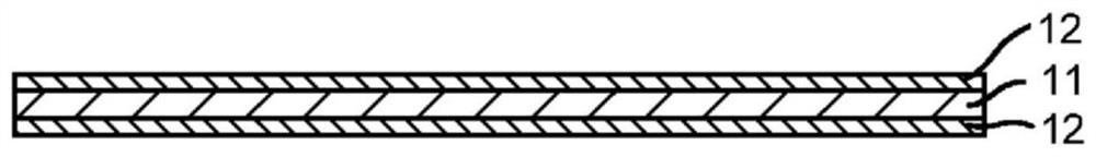
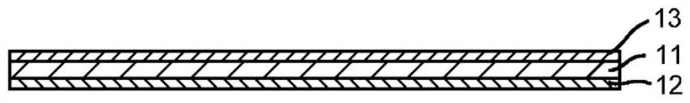
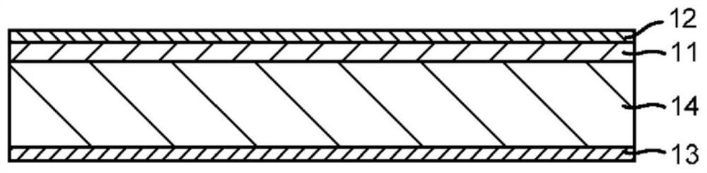
[0295] The obtained coating solution was applied to a glass (alkali-free glass; manufactured by Asahi Glass Co., Ltd., trade name: AN100) substrate with a thickness of 0.3 mm by spin coating, and heated and dried to form an absorption layer with a thickness of 0.9 μm to 1.1 μm. NIR filters composed of a transparent substrate and an absorbing layer (Example 1-1 to Example 1-10, Example 1-12) were obtained.

example 2-1~ example 2-7

[0297]The pigment shown in Table 5 in the obtained NIR pigment is mixed with polyimide resin (C3630) and the cyclohexanone solution prepared in the mixed solvent (cyclohexanone+NMP) and the NMP solution respectively. Stir and dissolve to obtain a coating liquid. In addition, in Example 2-6, the NIR dye (A2) used did not dissolve in the resin solution, and the coating liquid could not be prepared.

[0298] The obtained coating solution was coated on a glass (AN100) substrate with a thickness of 0.3 mm by spin coating, and heated and dried to form an absorption layer with a thickness of 0.9 to 1.2 μm to obtain a NIR filter (Example 2-1 to Example 2- 5, Example 2-7).


PUM

PropertyMeasurementUnit
thicknessaaaaaaaaaa
thicknessaaaaaaaaaa
thicknessaaaaaaaaaa

Abstract

An optical filter includes an absorption layer which increases a visible light transmittance while having a good near-infrared blocking characteristic, and which is excellent in not only adhesivenesswith respect to a layer to be abutted, but also light resistance. The optical filter includes the absorption layer containing a near-infrared absorption dye containing a squarylium-based dye and a transparent resin; and an inorganic or organic material in contact with the absorption layer. The squarylium-based dye has a squarylium skeleton and condensed ring structures bonded thereto respectivelyon both sides thereof, the condensed ring structures each including a benzene ring and a nitrogen atom as an annular atom, each benzene ring having an urethane structure in the second position.

Description

[0001] This application is a divisional application of the invention application with the application number 201680026755.6, the application date is May 11, 2016, and the invention name is "optical filter and imaging device". technical field [0002] The present invention relates to an optical filter that transmits visible light and shields near-infrared light, and an imaging device equipped with the optical filter. Background technique [0003] In imaging devices using solid-state imaging devices such as CCDs mounted in digital cameras, etc., optical filters (near-infrared cut filters) that transmit visible light and block near-infrared light have been used to reproduce color tones well and obtain sharp images. ). [0004] In particular, optical filters that use pigments that have high absorption in the near-infrared region and high transmittance in the visible light region can obtain steep shielding properties for near-infrared rays and obtain good colors for images of vis...

Claims


Application Information

Patent Timeline
Patent Type & Authority Applications(China)
IPC IPC(8): G02B5/20G02B5/22G02B1/04G01J1/04C09B57/00
CPCG02B5/208G01J1/0488G02B1/04C09B57/007G02B5/22H01L27/14625
Inventor 盐野和彦松浦启吾东田盛纱友梨保高弘树
Owner AGC INC
Why Eureka
Try Eureka