Ultra-wideband array antenna

An array antenna, ultra-wideband technology, applied in the field of radio frequency communication

Inactive Publication Date: 2019-04-12
XI AN JIAOTONG UNIV
View PDF8 Cites 2 Cited by
  • Summary
  • Abstract
  • Description
  • Claims
  • Application Information

AI Technical Summary

Problems solved by technology

In addition, some special requirements, such as the realization of beam scanning covering a wide range of airspace, etc., are often not met by a single antenna

Method used


Image

  • Ultra-wideband array antenna
  • Ultra-wideband array antenna
  • Ultra-wideband array antenna

Examples


Embodiment Construction

[0022] Certain terms are used throughout the specification and claims to refer to specific components. As can be understood by those skilled in the art, electronic device manufacturers may refer to the same component by different names. This article does not distinguish components by name, but by function. In the following description and claims, the word "comprising" is an open-ended restrictive word, so it should be interpreted as meaning "including but not limited to...". Additionally, the term "coupled" is intended to mean either an indirect electrical connection or a direct electrical connection. Thus, when one device couples to another device, that connection may be a direct electrical connection or an indirect electrical connection through other devices and connections.

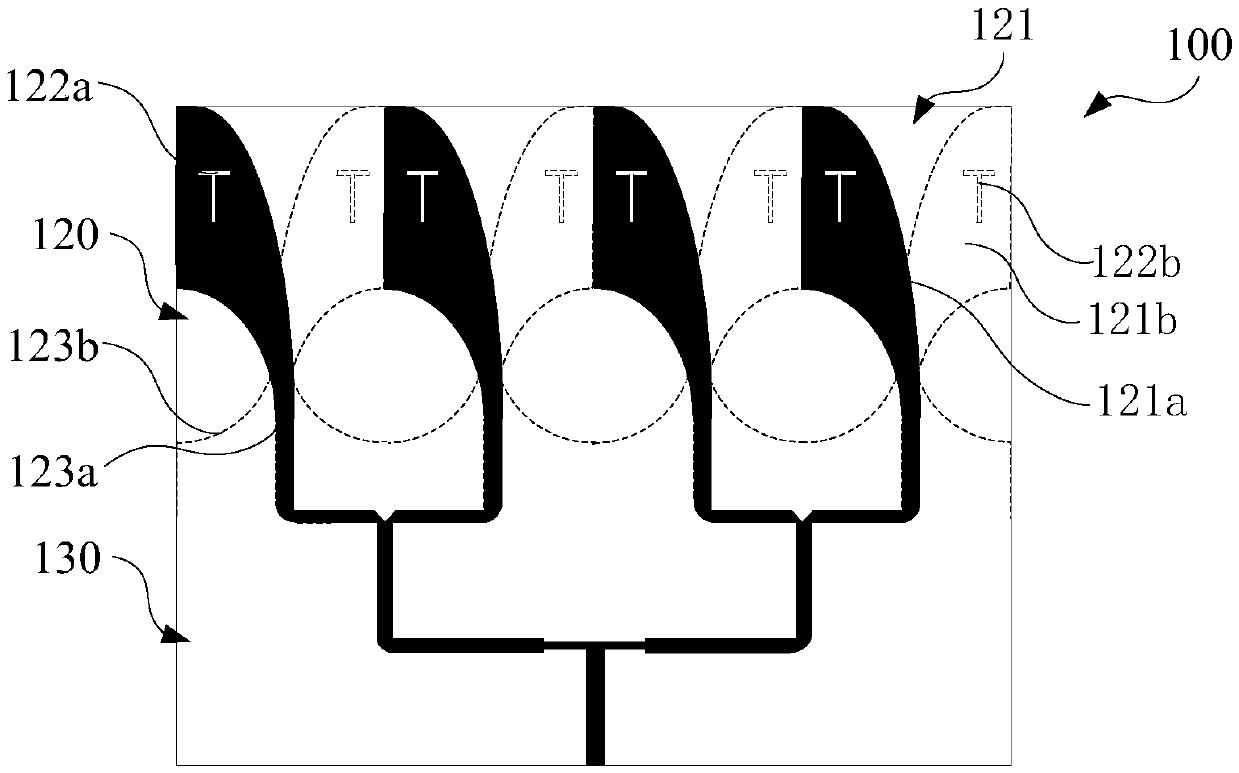
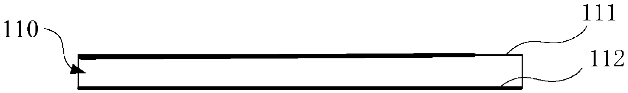
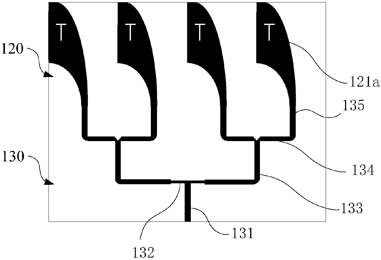
[0023] Such as Figure 1a and Figure 1b Shown is a schematic diagram of an ultra-wideband array antenna according to an embodiment of the present invention. The array antenna 100 includes a substr...


PUM


Abstract

The invention provides an ultra-wideband array antenna. The array antenna comprises a substrate, a radiation part and a feeding part, wherein the radiation part is arranged on the substrate and comprises a radiation array, the radiation array comprises n radiation units which are arranged in parallel, each radiation unit is an improved Vivaldi antenna unit and comprises a first radiation body anda second radiation body, the first radiation body and the second radiation body both are of one fourth ellipses, the first radiation body and the second radiation body are respectively arranged on a metal surface and a grounding surface of the substrate, are partially overlapped and are expanded towards opposite directions, and grooves are respectively formed in the first radiation body and the second radiation body. By the antenna structure, ultra-wideband, miniaturization and high gain can be achieved.

Description

technical field [0001] The disclosed embodiments of the present invention relate to the technical field of radio frequency communication, and more particularly, to an ultra-wideband array antenna. Background technique [0002] In recent years, people's demand for wireless communication services (5G, WLAN, radio, television, etc.) has increased rapidly, and limited spectrum resources have been unable to meet the rapidly growing demand. The ultra-wideband technology has the advantages of high communication rate, large system capacity, strong anti-interference ability, high resolution, simple system, and low cost. It can well deal with the contradiction between people's growing information needs and limited spectrum resources. And get more and more attention. In addition, some special requirements, such as realizing beam scanning to cover a wide range of airspace, etc., are often not met by a single antenna. [0003] According to the theory of electromagnetic wave space inter...

Claims


Application Information

Patent Timeline
Patent Type & Authority Applications(China)
IPC IPC(8): H01Q1/38H01Q1/48H01Q1/50H01Q21/06
Inventor 刘海文杜黎霞文品
Owner XI AN JIAOTONG UNIV
Why Eureka
Try Eureka