Millimeter wave power detection circuit

A power detection circuit and millimeter wave technology, applied in the field of radar, can solve problems such as the inability to meet the design requirements of component miniaturization, and achieve the effect of reducing the volume

Inactive Publication Date: 2020-02-11
CNGC INST NO 206 OF CHINA ARMS IND GRP
View PDF7 Cites 0 Cited by
  • Summary
  • Abstract
  • Description
  • Claims
  • Application Information

AI Technical Summary

Problems solved by technology

With the increasing miniaturization requirements of transceiver components, waveguide slot coupling and coaxial probe coupling can no longer meet the design requirements of component miniaturization due to volume and size limitations.

Method used


Image

  • Millimeter wave power detection circuit
  • Millimeter wave power detection circuit
  • Millimeter wave power detection circuit

Examples


Embodiment Construction

[0023] Now in conjunction with embodiment, accompanying drawing, the present invention will be further described:

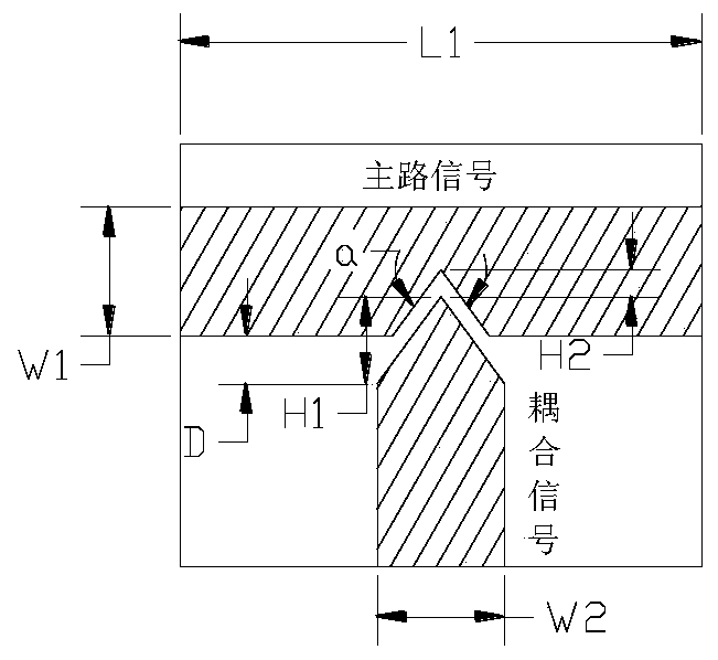
[0024] The present invention is based on the microstrip coupling mode. The wave transmitted in the microstrip line is a quasi-TEM wave, and its electric field is mainly concentrated between the conductor strip and the ground plate. When two microstrip lines exist at the same time and are relatively close to each other, There will be a part of the electromagnetic field to couple the two microstrips; if the two microstrips are far apart, in general, when the distance is greater than 4 times the width of the microstrip, the coupling between the microstrips will be very weak, which can be seen into two independent microstrip lines.

[0025] When analyzing coupled microstrip lines, any two microstrip lines are often decomposed into the sum of even-mode and odd-mode excitations. For the even-mode excitation, the electric field distribution of the two microstrip lines ...


PUM


Abstract

The invention relates to a millimeter wave power detection circuit mainly applied to the field needing power detection in a millimeter wave transmitting-receiving assembly. A main path signal is coupled in a microstrip mode in design, the coupled signal passes a detection circuit and a comparison circuit, a power signal is converted into a 3.3V TTL signal, the 3.3V TTL signal is reported to detectthe transmitting power of the transmitting-receiving assembly. The detection circuit provided by the invention is highly reliable and consistent.

Description

technical field [0001] The invention relates to the field of radar technology, in particular to the problem of power detection in millimeter wave transceiver components. Background technique [0002] In the radar system, the transmission power of the transceiver component is one of the key indicators, and the transmission power will directly affect the range of the radar. [0003] In an actual application system, it is often impossible to directly test the transmit power of the transceiver component, which requires coupling and detection of the transmit power of the transceiver component through power coupling. On the one hand, the coupling detection signal can be used as a criterion for whether the transmit power of the component is normal or not, and on the other hand, it can be used as a report signal to monitor the transmit power of the component in real time. [0004] In the power detection circuit, the commonly used power detection forms are: microstrip coupling, wave...

Claims


Application Information

Patent Timeline
Patent Type & Authority Applications(China)
IPC IPC(8): G01S7/40
CPCG01S7/4004
Inventor 张国强武华锋李磊马云柱李峰李锐
Owner CNGC INST NO 206 OF CHINA ARMS IND GRP
Why Eureka
Try Eureka