CTS frequency sweep antenna with large frequency sweep ratio

A technology of frequency scanning and antenna, which is applied in the direction of antenna, radiating element structure, waveguide device, etc., can solve the problems of limited improvement of frequency scanning ratio, limited beam mitigation effect, limited space for beam scanning angle improvement, etc.

Active Publication Date: 2019-05-14
NINGBO UNIV
View PDF9 Cites 6 Cited by
  • Summary
  • Abstract
  • Description
  • Claims
  • Application Information

AI Technical Summary

Problems solved by technology

Because the antenna uses a comb structure added to the waveguide to achieve angular scanning, the effect on beam mitigation is limited, and due to the limitation of the profile he

Method used


Image

  • CTS frequency sweep antenna with large frequency sweep ratio
  • CTS frequency sweep antenna with large frequency sweep ratio
  • CTS frequency sweep antenna with large frequency sweep ratio

Examples


Embodiment

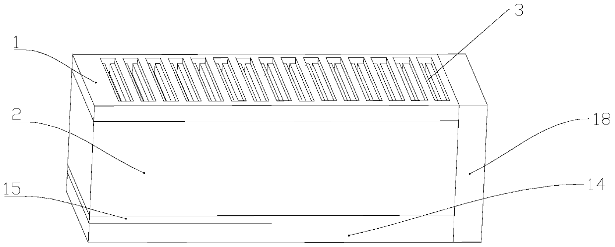
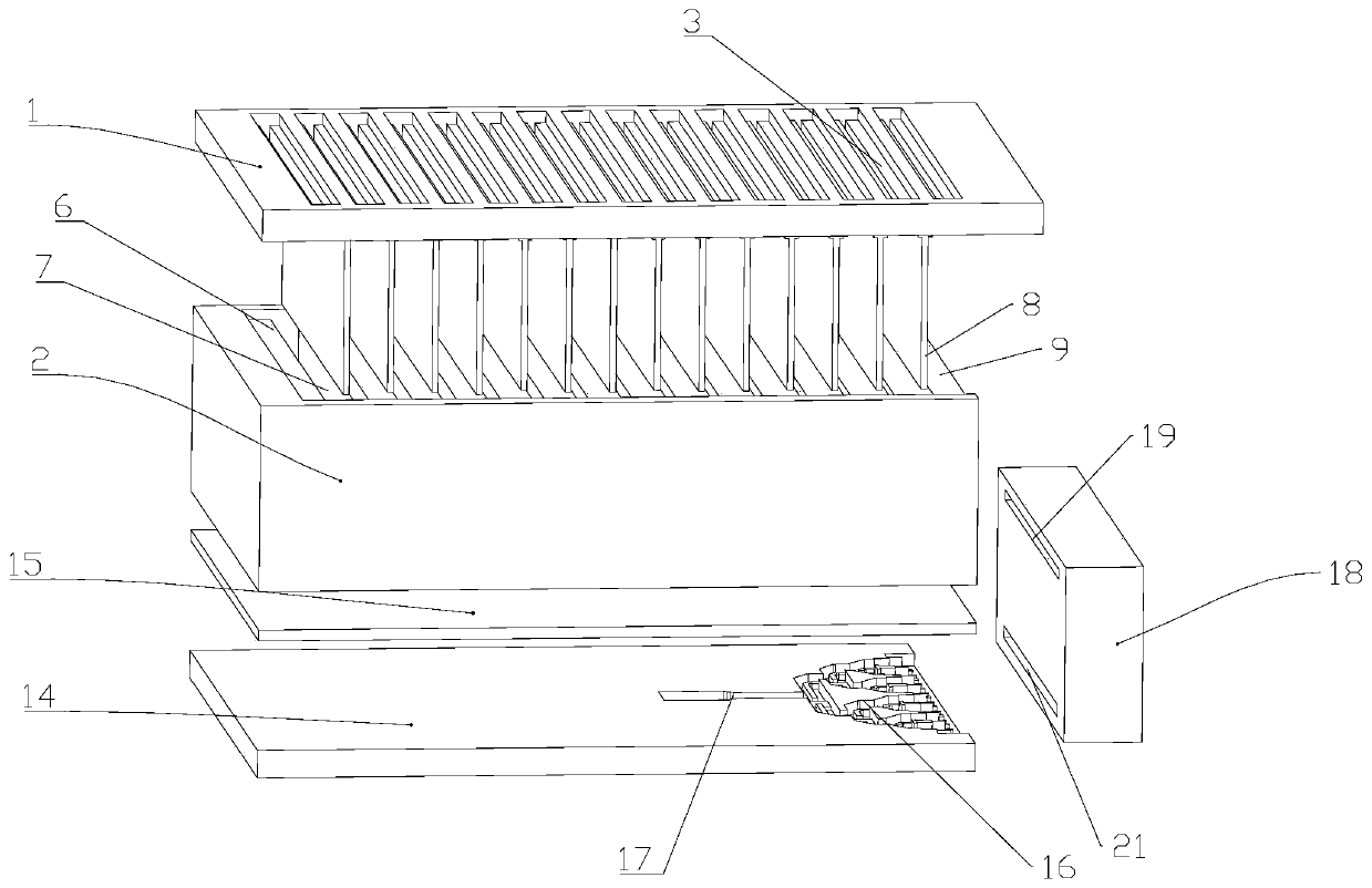
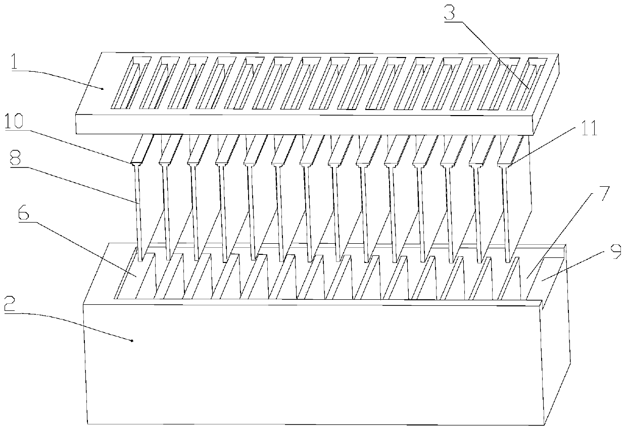
[0031] Example: such as Figure 1-Figure 10 As shown, a CTS frequency scanning antenna with a large frequency scanning ratio includes a radiation layer and a broadband line source layer arranged in sequence from top to bottom, and the broadband line source layer is used to convert electromagnetic waves of different frequencies input into it The plane waves of different frequencies are transmitted to the radiation layer, and the radiation layer is used to radiate the plane waves of different frequencies transmitted into it to the free space at different beam angles. The radiation layer is realized by a non-uniform meandering slow wave structure.

[0032] In this embodiment, the radiation layer includes a first metal block 1 and a second metal block 2, both of which are rectangular; the first metal block 1 is provided with 15 continuous lateral branches 3, 15 continuous transverse branches 3 are arranged at even intervals from left to right, and the distance between every two ad...


PUM

PropertyMeasurementUnit
Diameteraaaaaaaaaa

Abstract

The invention discloses a CTS frequency sweep antenna with a large frequency sweep ratio. The CTS frequency sweep antenna comprises a radiation layer and a broadband line source layer which are sequentially arranged from the top down, the broadband line source layer is used for converting electromagnetic waves which are input into the broadband line source layer and at different frequencies into plane waves at different frequencies and transmitting the plane waves to the radiation layer, the radiation layer is used for radiating the plane waves which are transmitted into the radiation layer and at different frequencies to a free space in different beam angles, and the radiation layer is realized by adopting a nonuniform zigzag slow-wave structure. The CTS frequency sweep antenna disclosedby the invention has the advantages that a beam scanning angle in a frequency band range is relatively large and the frequency sweep ratio is relatively high.

Description

technical field [0001] The invention relates to a CTS frequency scanning antenna, in particular to a CTS frequency scanning antenna with a large frequency scanning ratio. Background technique [0002] The scanning antenna is an antenna that controls the beam pointing of the radar antenna in a certain way and completes the beam scanning, such as the millimeter wave imaging system in the security inspection system, the detection antenna in the remote sensing detection field, and the missile detection device in the military radar. Antenna involvement. [0003] Traditional scanning antennas are mostly mechanical scanning antennas, which control the orientation and deflection angle of the antenna through mechanical devices to achieve the purpose of scanning. Due to poor stability and slow beamforming, mechanical scanning antennas have narrow application fields, and have been gradually replaced by emerging electronic scanning antennas. Phase scanning antennas and frequency scann...

Claims


Application Information

Patent Timeline
IPC IPC(8): H01Q23/00H01Q1/36H01P5/10
Inventor 周国良黄季甫尤阳方陈剑尤清春陆云龙钟硕敏
Owner NINGBO UNIV
Why Eureka
Try Eureka